EN
EN


PCB Transformer Manufacturer for Custom OEM Applications
ECKO designs and manufactures PCB-mounted transformers based on your electrical requirements, dimensional limits and applicable safety standards.
| Parameter | Typical Range / Available Options |
|---|---|
| Product Type | Open-frame, vacuum-impregnated or fully encapsulated PCB transformer |
| Rated Power | 0.5 VA to 20 VA typical; higher ratings subject to engineering review |
| Primary Voltage | 100V, 110V, 115V, 120V, 200V, 220V, 230V or 240V AC; single or dual primary |
| Secondary Voltage | 3V to 48V AC per winding typical; other voltages available |
| Output Configuration | Single, center-tapped, dual or multiple secondary windings |
| Frequency | 50Hz, 60Hz or 50/60Hz |
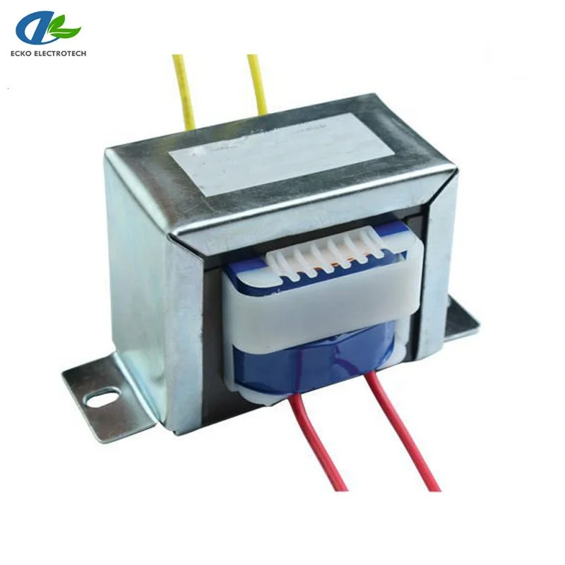
| Core Material | EI laminated electrical steel core selected according to power and temperature-rise requirements |
| Winding Material | Copper winding wire |
| Insulation Class | Class B 130°C or Class F 155°C |
| Dielectric Strength | Project-specific; 3.0–4.0kVAC primary-to-secondary options commonly available |
| Temperature Rise | Defined according to rated load, ambient temperature, enclosure and insulation class |
| Pin Configuration | Custom pin count, pitch, row spacing, diameter, length and polarity marking |
| Protection Options | Thermal fuse, resettable thermal protector or external PTC coordination |
- Overview
- Recommended Products
- Visual Inspection: Routine or sampling
- Dimensional Inspection: Sampling, with critical dimensions controlled as specified
- Winding Resistance: Routine test
- Turns Ratio / Output Voltage: 100% routine test
- No-Load Current: 100% or agreed inspection plan
- No-Load Loss: Sampling or qualification
- Load Voltage and Regulation: Sample and periodic verification
- Insulation Resistance: Routine or sampling
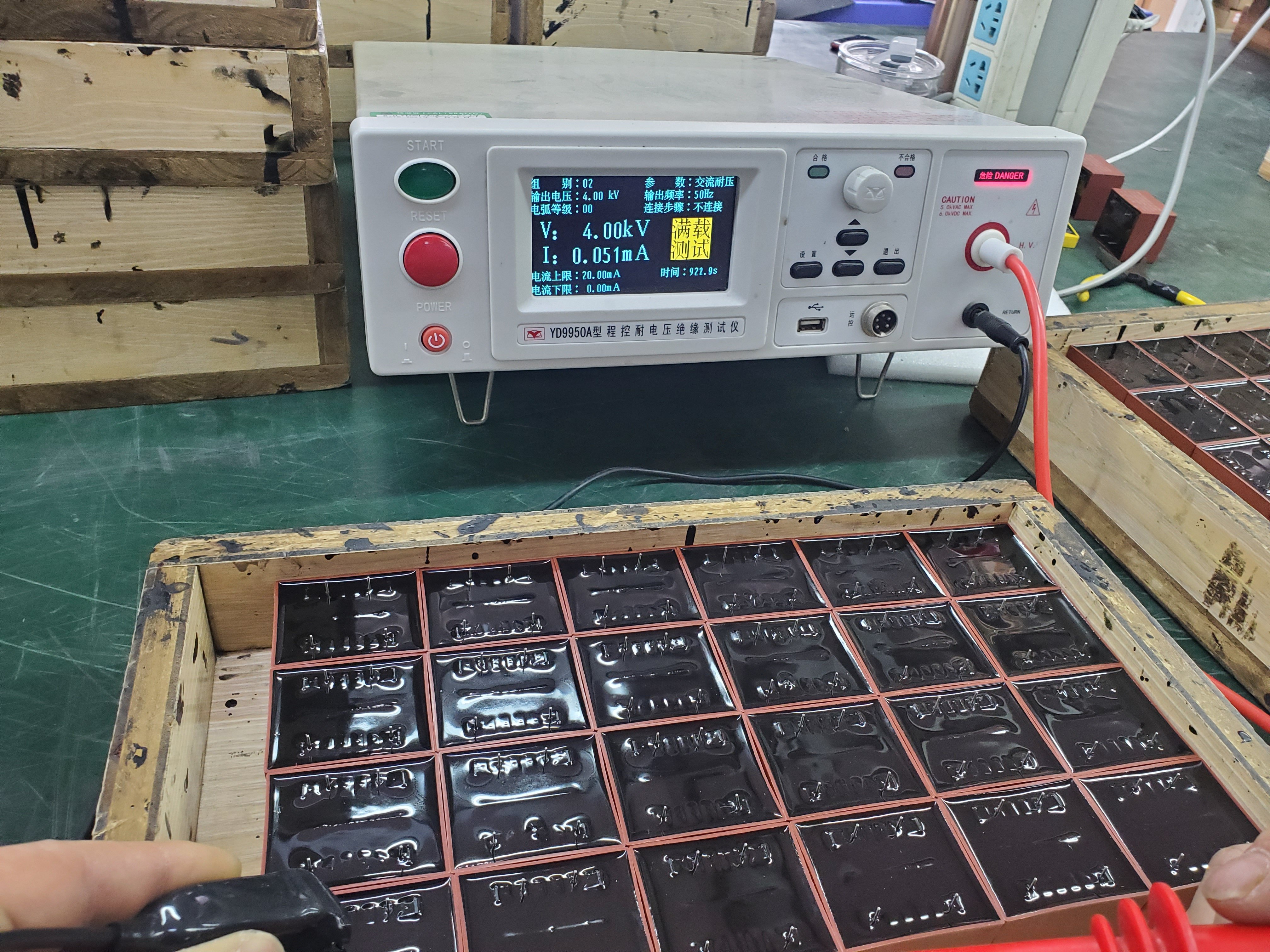
- Dielectric Strength / Hi-Pot: 100% at the approved test level
- Temperature Rise: Type or qualification test
- Audible Noise: When required by the approved specification
- Solderability: Qualification or sampling
- Resistance to Soldering Heat: Verified according to the project requirement
Custom PCB Transformers Engineered for Your Circuit Board
Compact through-hole PCB transformers with customized input voltage, output windings, rated power, pin layout and insulation construction. ECKO designs each transformer around your load requirements, PCB footprint, temperature-rise target and applicable safety requirements.
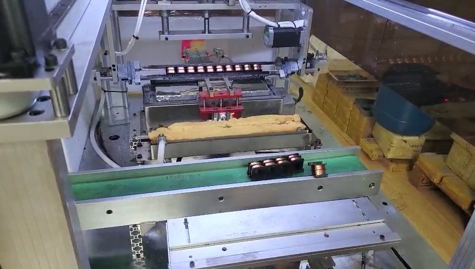
From initial electrical calculations to approved drawings, controlled production and routine electrical testing, we help OEM customers integrate reliable mains-frequency power conversion directly into their PCB assemblies.
Typical PCB Transformer Specifications
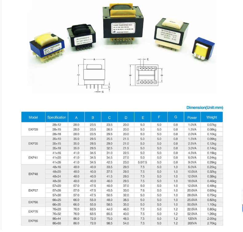
Specification notice: The values above represent typical engineering capabilities rather than one fixed catalog model. Final electrical ratings, dimensions, tolerances and test limits are defined by the customer-approved specification and dimensional drawing.
PCB Transformer Product Advantages
PCB Transformer Customization Options
|
Electrical Input |
Electrical Output |
Rated Power |
PCB Footprint |
|
Product Dimensions |
Insulation System |
Dielectric Strength |
Thermal Protection |
|
Environmental Protection |
Noise Control |
Documentation |
Packaging |












Why Choose ECKO for Custom PCB Transformers?
PCB Transformer Tests and Reference Standards
From winding continuity and output voltage to insulation withstand, temperature rise and solderability, ECKO verifies each PCB transformer according to the approved drawing, test specification and inspection plan.
Routine Production Tests
|
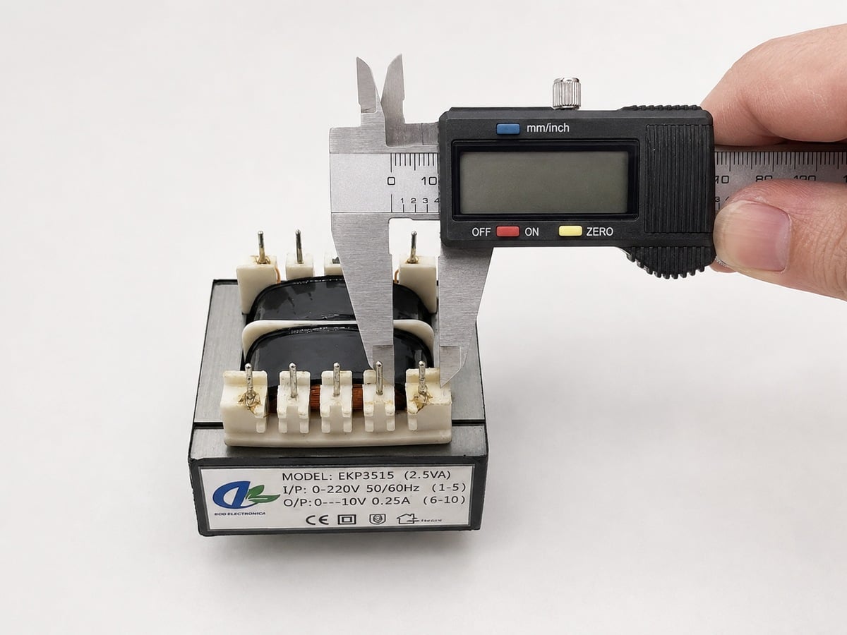
Visual and Dimensional Inspection Workmanship, labels, polarity marks, pin condition, outline dimensions, seated height, pin pitch and pin position are checked against the approved drawing. |
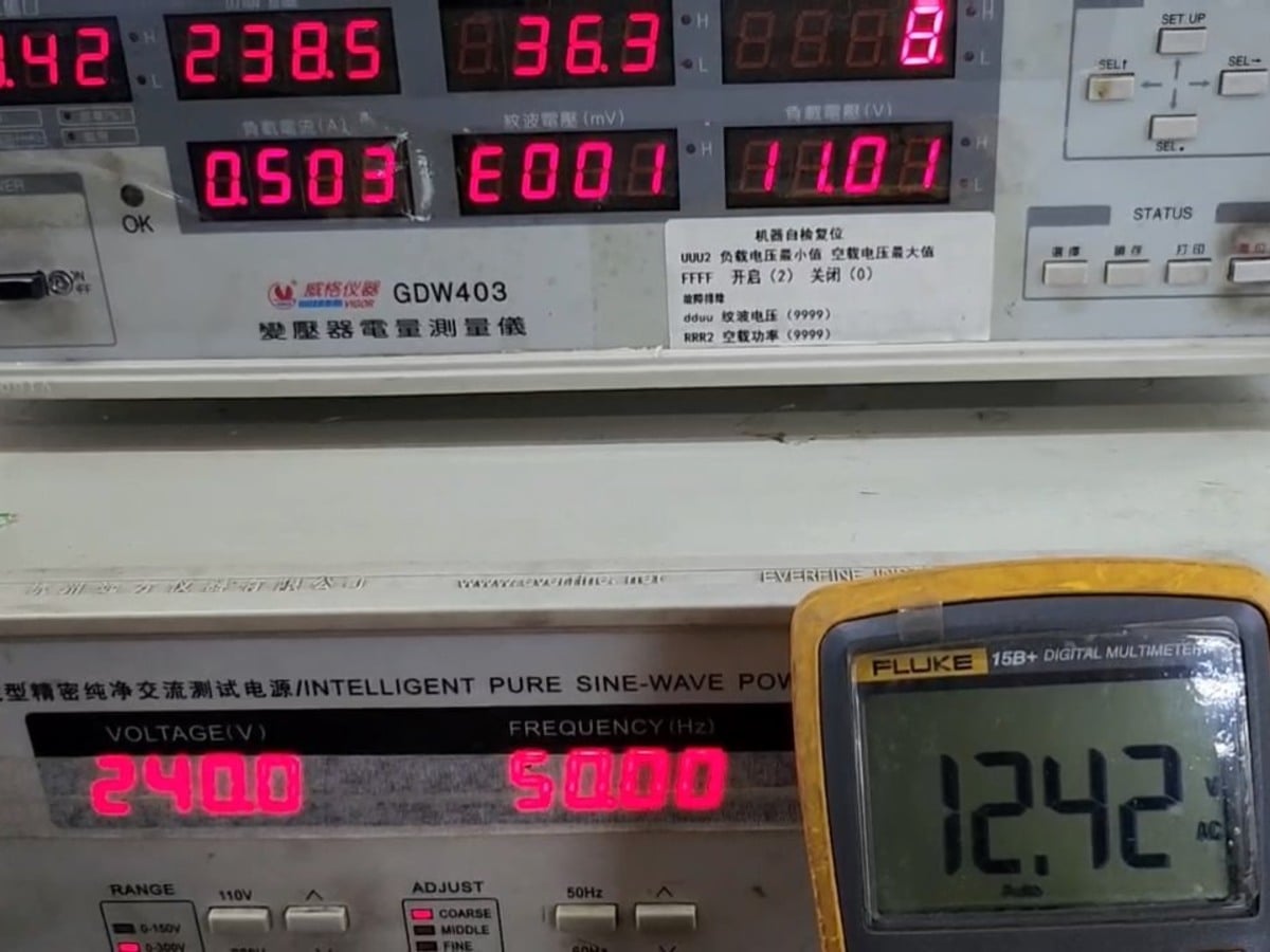
Winding and Output Verification Winding resistance testing checks conductor continuity and manufacturing consistency. Turns-ratio and output-voltage testing confirm the required secondary voltage and winding polarity at the specified primary input. |
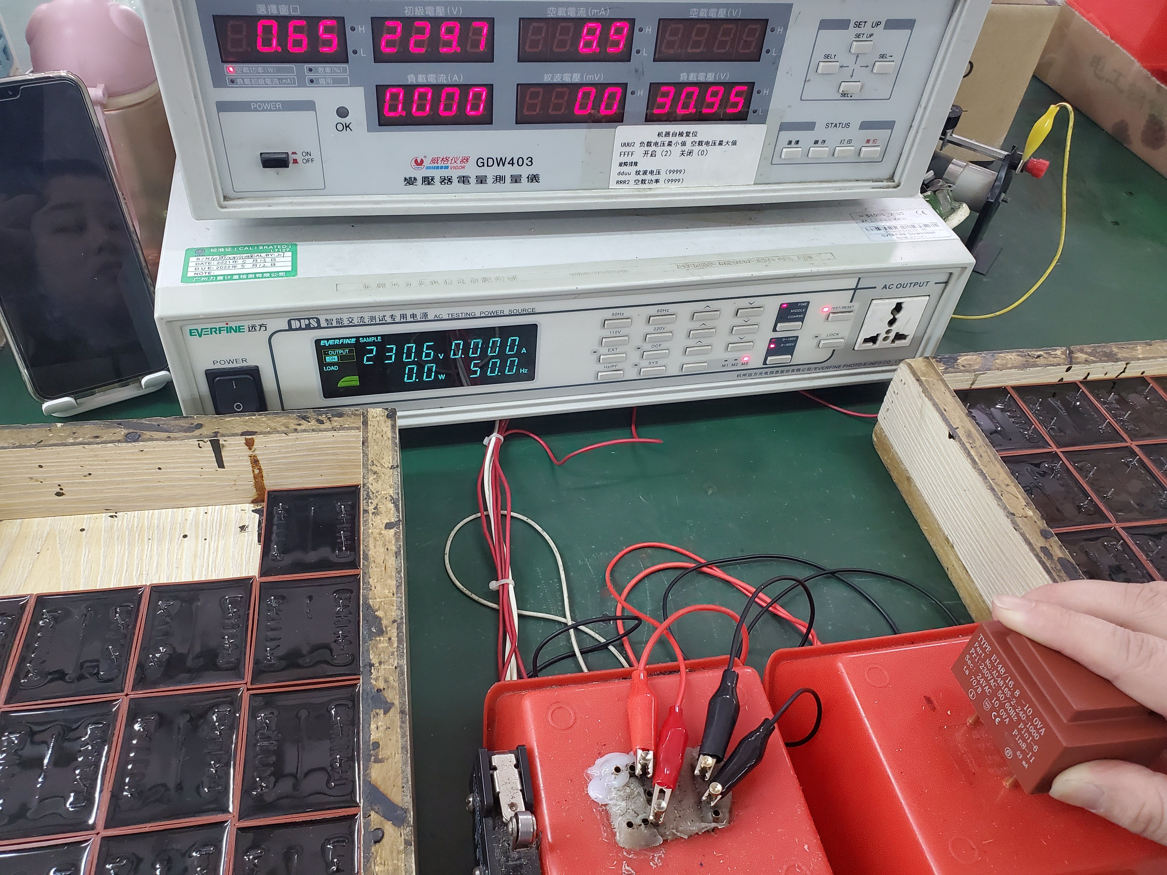
No-Load and Rated-Load Performance No-load current and no-load loss are evaluated to confirm core assembly, winding consistency and standby performance. Rated-load voltage and regulation are verified under defined input and load conditions. |
|
Insulation Safety Testing Insulation resistance testing checks electrical separation between windings and accessible conductive parts. Dielectric strength testing verifies the specified insulation withstand level at the approved voltage and duration. |
Temperature Rise and Audible Noise Temperature-rise testing verifies thermal performance under defined mounting, ambient and load conditions. Audible-noise evaluation is performed when transformer hum or mechanical vibration is controlled by the project specification. |
PCB Pin Solderability PCB pin wetting and resistance to soldering heat are evaluated to support stable PCB assembly and repeatable solder-joint quality. |
Custom PCB Transformer Development Process
PCB Transformer FAQ
1. What information is required to quote a custom PCB transformer?
Please provide the input voltage and frequency, each output voltage and current, rated power or load profile, maximum dimensions, PCB footprint, operating temperature, insulation requirements, annual quantity and applicable safety standard. A PCB file, existing drawing or product sample is also helpful.
2. How do I calculate the required transformer VA rating?
For each secondary winding, multiply the rated output voltage by the required output current. Add the VA values of all windings and include suitable design margin for regulation, temperature rise, intermittent peak loads and rectifier circuits.
3. Can you produce 115V/230V dual-primary PCB transformers?
Two primary windings can be configured for series or parallel connection to support different mains voltages. The pin assignment, connection diagram and insulation requirements must be confirmed on the approved drawing.
4. Can one PCB transformer provide multiple output voltages?
We can design single, dual, center-tapped or multiple independent secondary windings. Please specify the voltage, current and duty cycle required from each winding.
5. What is the difference between an open-frame and an encapsulated PCB transformer?
An open-frame transformer is generally smaller, lighter and more economical. A fully encapsulated transformer provides better protection against moisture, dust and mechanical vibration, but normally has different thermal behavior, dimensions and tooling requirements.
6. Can you match our existing PCB footprint?
We can review your PCB layout, hole positions, keep-out area and maximum component height. Final pin tolerances and PCB hole diameters should be confirmed through an approved dimensional drawing.
7. Can the transformer dimensions be customized?
Within the limits of electrical power, insulation distance, core size and temperature rise. Reducing one dimension may require increasing another dimension or accepting different thermal and regulation performance.
8. What is the typical temperature rise of a PCB transformer?
Temperature rise is not one fixed value for every model. It depends on the VA rating, ambient temperature, enclosure ventilation, core flux density, winding current density and insulation class. ECKO can design to an agreed maximum temperature-rise target and verify it on the sample.
9. Can you reduce no-load current, standby loss or audible hum?
Yes. These characteristics can be improved through core selection, increased turns, lower flux density, controlled core assembly, winding arrangement and impregnation. The required limits should be stated before the transformer size and price are finalized.
10. Can you add an electrostatic shield?
A shield can be placed between the primary and secondary windings to reduce capacitive coupling and common-mode noise. The shield lead and grounding method must be shown in the customer’s circuit and pin diagram.