EN
EN

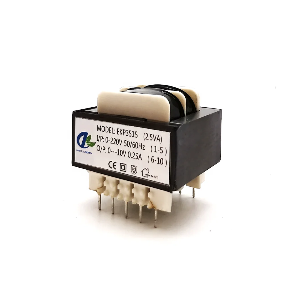
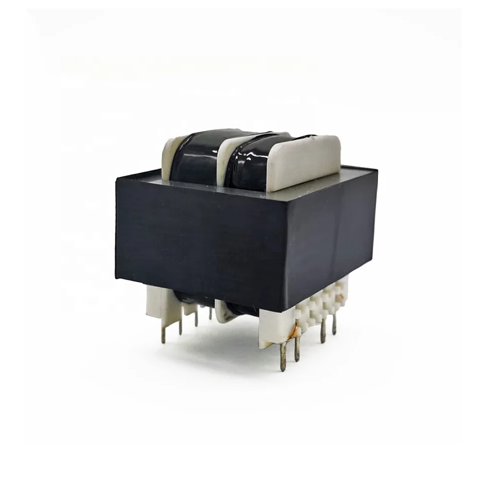
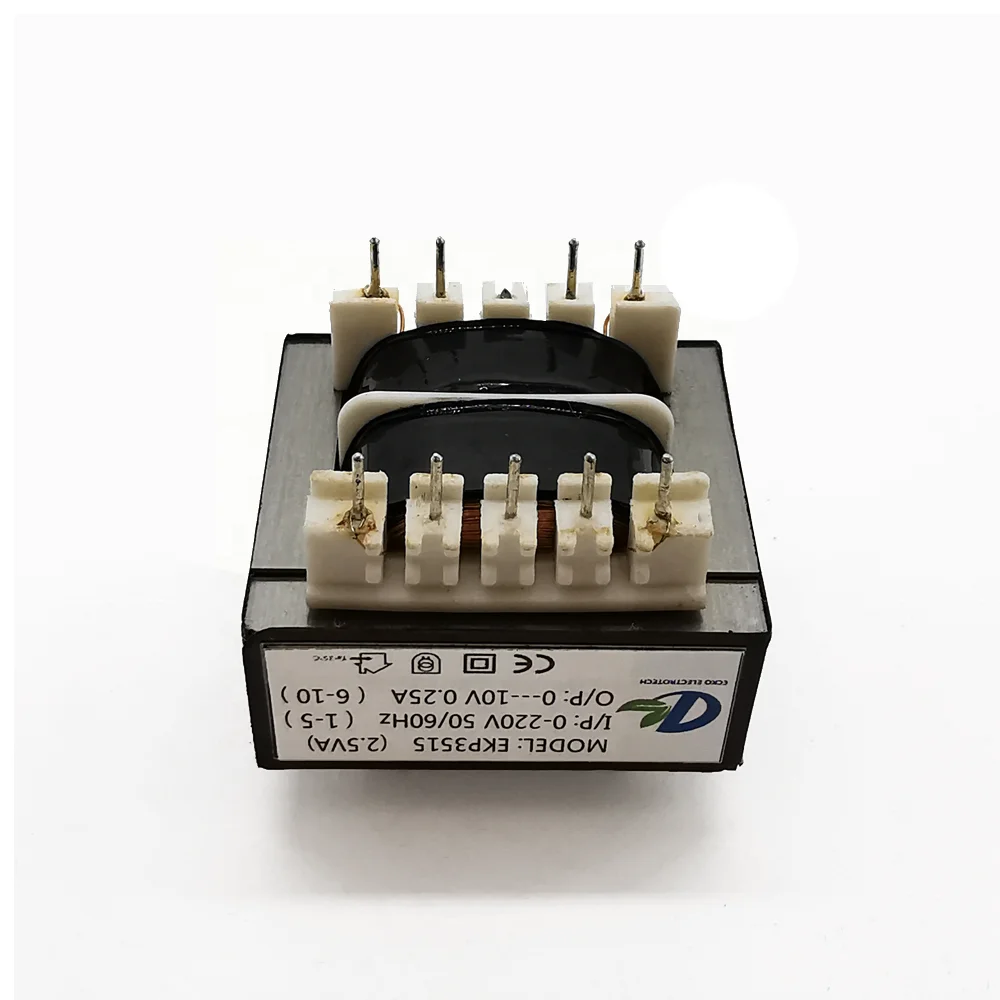
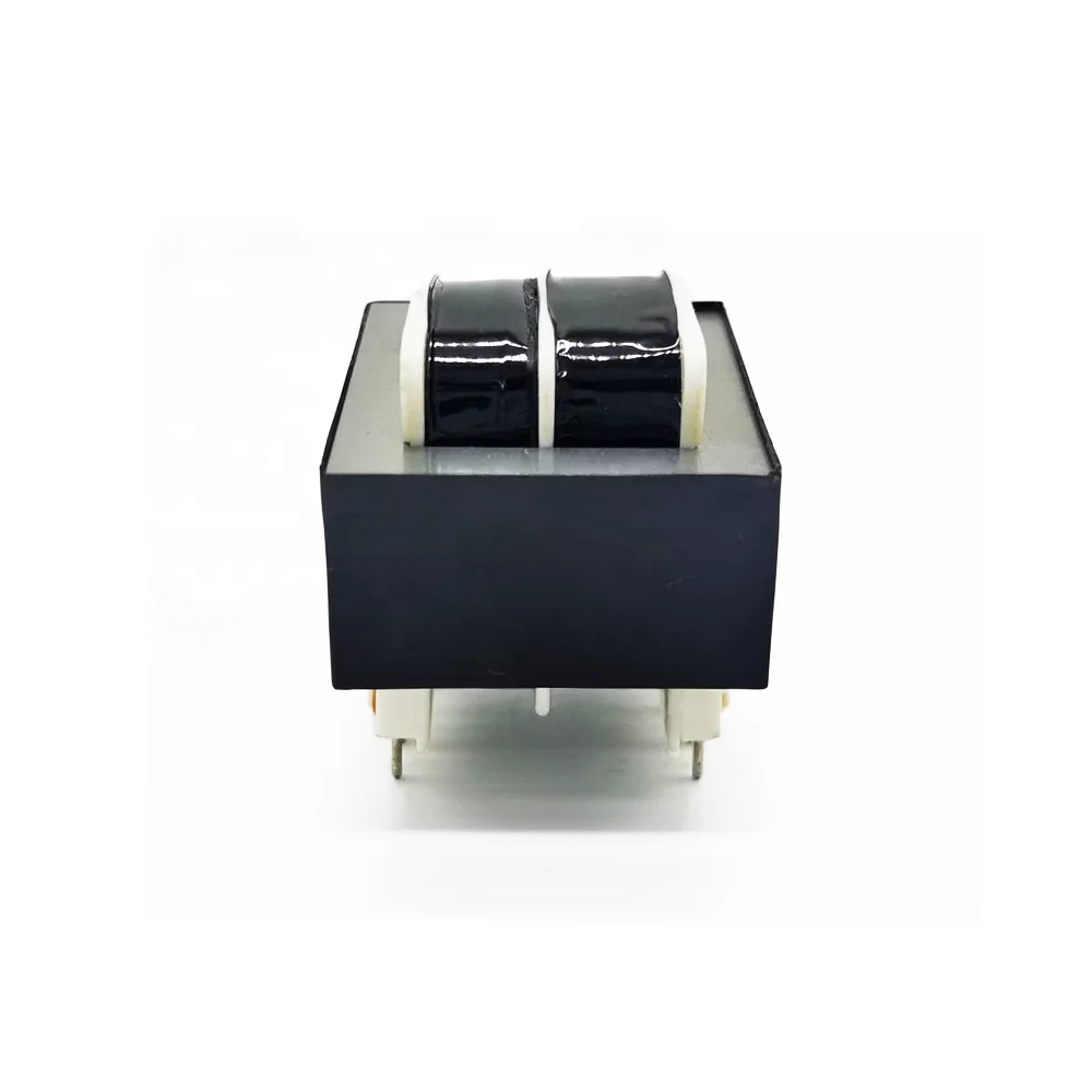
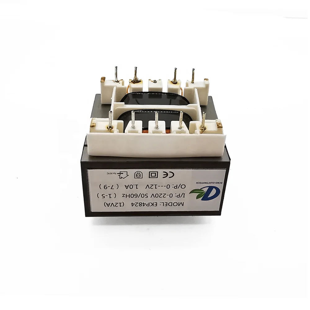
संकुचित शक्ति आपूर्ति डिज़ाइन के लिए अनुकूलित ईआई पीसीबी ट्रांसफॉर्मर
विश्वसनीय ओईएम सर्किट बोर्ड में एकीकरण के लिए अनुकूलित इनपुट वोल्टेज, आउटपुट वाइंडिंग, रेटेड पावर और पिन लेआउट के साथ इंजीनियर्ड।
| पैरामीटर | सामान्य सीमा / उपलब्ध विकल्प |
|---|---|
| उत्पाद प्रकार | खुला-फ्रेम, वैक्यूम-आरोपित या पूर्ण रूप से संलग्न पीसीबी ट्रांसफॉर्मर |
| अंकित शक्ति | 0.5 वीए से 30 वीए तक सामान्य; उच्च रेटिंग के मामले में इंजीनियरिंग समीक्षा आवश्यक |
| प्राथमिक वोल्टेज | 100V, 110V, 115V, 120V, 200V, 220V, 230V या 240V AC; एकल या द्वैत प्राथमिक |
| द्वितीयक वोल्टेज | प्रति वाइंडिंग 3V से 48V AC तक सामान्य; अन्य वोल्टेज उपलब्ध |
| आउटपुट कॉन्फ़िगरेशन | एकल, केंद्र-टैप, द्वैत या बहु-द्वितीयक वाइंडिंग्स |
| आवृत्ति | 50हर्ट्ज़, 60हर्ट्ज़ या 50/60हर्ट्ज़ |
| कोर सामग्री | शक्ति और तापमान-वृद्धि आवश्यकताओं के अनुसार चुना गया EI लैमिनेटेड विद्युत इस्पात कोर |
| वाइन्डिंग मटेरियल | पीतलू विंडिंग तार |
| इंसुलेशन क्लास | वर्ग B 130°C या वर्ग F 155°C |
| डाइलेक्ट्रिक ताकत | परियोजना-विशिष्ट; 3.0–4.0kVAC प्राथमिक से द्वितीयक विकल्प आमतौर पर उपलब्ध |
| तापमान वृद्धि | नामांकित भार, वातावरण का तापमान, आवरण और विद्युतरोधन श्रेणी के अनुसार परिभाषित |
| माउंटिंग मेथड | थ्रू-होल PCB पिन |
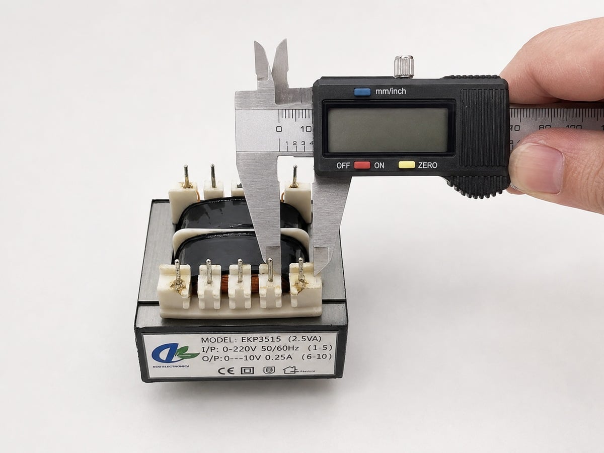
| पिन कॉन्फ़िगरेशन | अनुकूलित पिन संख्या, पिच, पंक्ति अंतराल, व्यास, लंबाई और ध्रुवता अंकन |
| सुरक्षा विकल्प | तापीय फ्यूज़, पुनः सेट करने योग्य तापीय सुरक्षा उपकरण या बाहरी PTC समन्वय |
| कवचन विकल्प | आवश्यकता होने पर इलेक्ट्रोस्टैटिक कवच, अंतर-वाइंडिंग कवच या चुंबकीय कवचन |
| परिचालन तापमान | सामान्य डिज़ाइन सीमा -20°C से +70°C तक, जो सामग्री प्रणाली पर निर्भर करती है |
| अनुपालन विकल्प | निर्माण लागू IEC, EN या UL आवश्यकताओं के लिए डिज़ाइन किया गया है; मंजूरी मॉडल-विशिष्ट है |
- अवलोकन
- अनुशंसित उत्पाद
- दृश्य जाँच: नियमित या नमूना आधार पर
- आयामी जाँच: नमूना लेना, जिसमें महत्वपूर्ण आयामों को निर्दिष्ट अनुसार नियंत्रित किया जाता है
- वाइंडिंग प्रतिरोध: दैनिक परीक्षण
- टर्न्स रेशियो / आउटपुट वोल्टेज: 100% नियमित परीक्षण
- नो-लोड धारा: 100% या सहमत निरीक्षण योजना
- नो-लोड हानि: नमूना या योग्यता प्रमाणन
- लोड वोल्टेज और विनियमन: नमूना और आवधिक सत्यापन
- इन्सुलेशन प्रतिरोध: नियमित या नमूना आधार पर
- डाइइलेक्ट्रिक स्ट्रेंथ / हाई-पॉट: अनुमोदित परीक्षण स्तर पर १००%
- तापमान वृद्धि: प्रकार या योग्यता परीक्षण
- श्रव्य शोर: जब अनुमोदित विनिर्देश द्वारा आवश्यक हो
- सॉल्डरेबिलिटी: योग्यता या नमूना लेना
- सॉल्डरिंग ऊष्मा के प्रति प्रतिरोध: परियोजना आवश्यकता के अनुसार सत्यापित
आपके सर्किट बोर्ड के लिए इंजीनियर किए गए कस्टम पीसीबी ट्रांसफॉर्मर
संक्षिप्त थ्रू-होल पीसीबी ट्रांसफॉर्मर जिसका इनपुट वोल्टेज, आउटपुट वाइंडिंग्स, रेटेड पावर, पिन लेआउट और इन्सुलेशन निर्माण अनुकूलित किया गया है। ईसीको प्रत्येक ट्रांसफॉर्मर को आपकी लोड आवश्यकताओं, पीसीबी फुटप्रिंट, तापमान वृद्धि के लक्ष्य और लागू सुरक्षा आवश्यकताओं के आधार पर डिज़ाइन करता है।
प्रारंभिक विद्युत गणनाओं से लेकर स्वीकृत आरेखों, नियंत्रित उत्पादन और नियमित विद्युत परीक्षण तक, हम ओईएम ग्राहकों को अपने पीसीबी असेंबलियों में विश्वसनीय मुख्य-आवृत्ति शक्ति परिवर्तन को सीधे एकीकृत करने में सहायता प्रदान करते हैं।
सामान्य पीसीबी ट्रांसफॉर्मर विनिर्देश
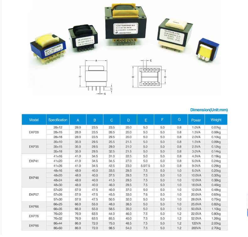
विशिष्टता सूचना: उपरोक्त मान एक निश्चित कैटलॉग मॉडल के बजाय सामान्य इंजीनियरिंग क्षमताओं का प्रतिनिधित्व करते हैं। अंतिम विद्युत रेटिंग, आयाम, सहिष्णुता और परीक्षण सीमाएँ ग्राहक-स्वीकृत विशिष्टता और आयामी ड्राइंग द्वारा परिभाषित की जाती हैं।
पीसीबी ट्रांसफॉर्मर उत्पाद लाभ
पीसीबी ट्रांसफॉर्मर के अनुकूलन विकल्प
|
विद्युत इनपुट |
विद्युत आउटपुट |
अंकित शक्ति |
पीसीबी फुटप्रिंट |
|
उत्पाद आयाम |
इन्सुलेशन सिस्टम |
डाइलेक्ट्रिक ताकत |
थर्मल सुरक्षा |
|
पर्यावरण संरक्षण |
शोर नियंत्रण |
डॉक्यूमेंटेशन |
पैकेजिंग |












कस्टम पीसीबी ट्रांसफॉर्मर के लिए ईको क्यों चुनें?
पीसीबी ट्रांसफॉर्मर परीक्षण और संदर्भ मानक
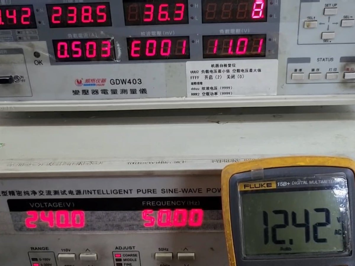
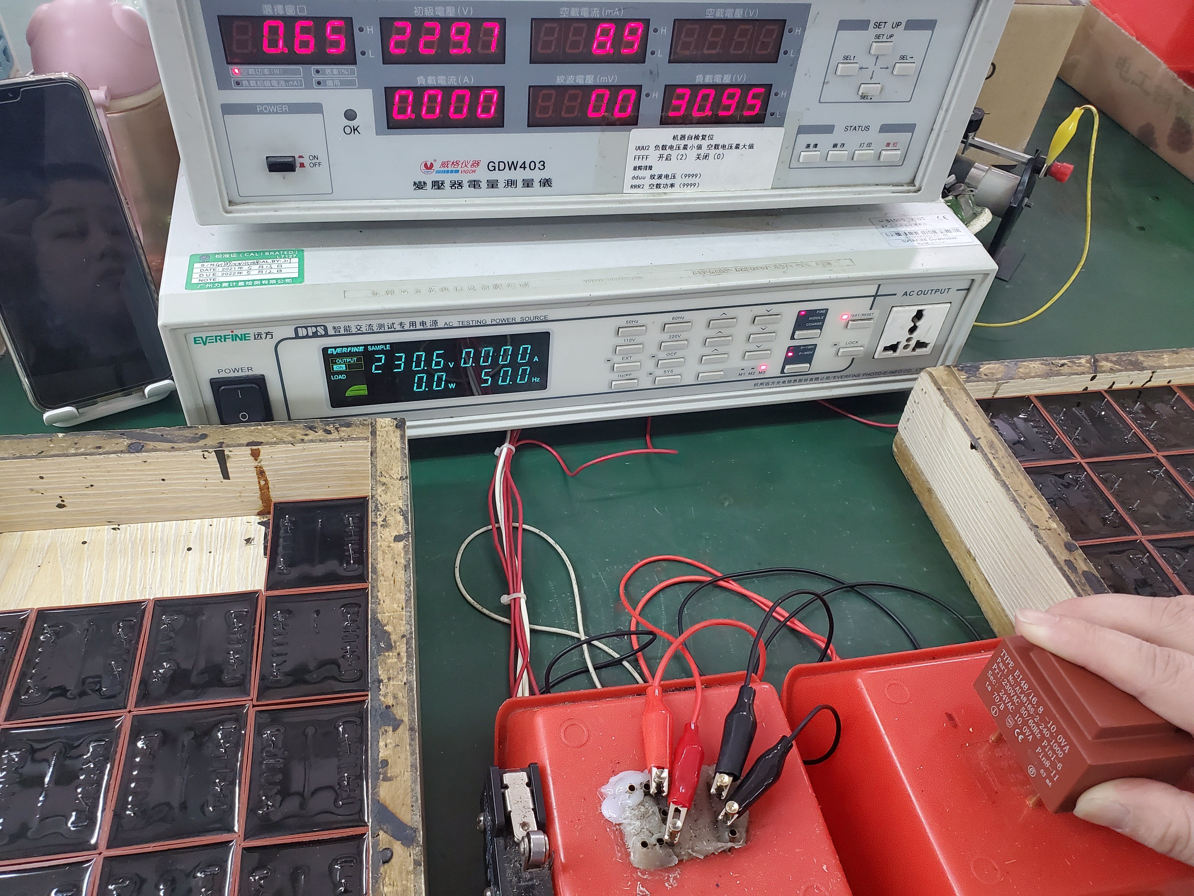
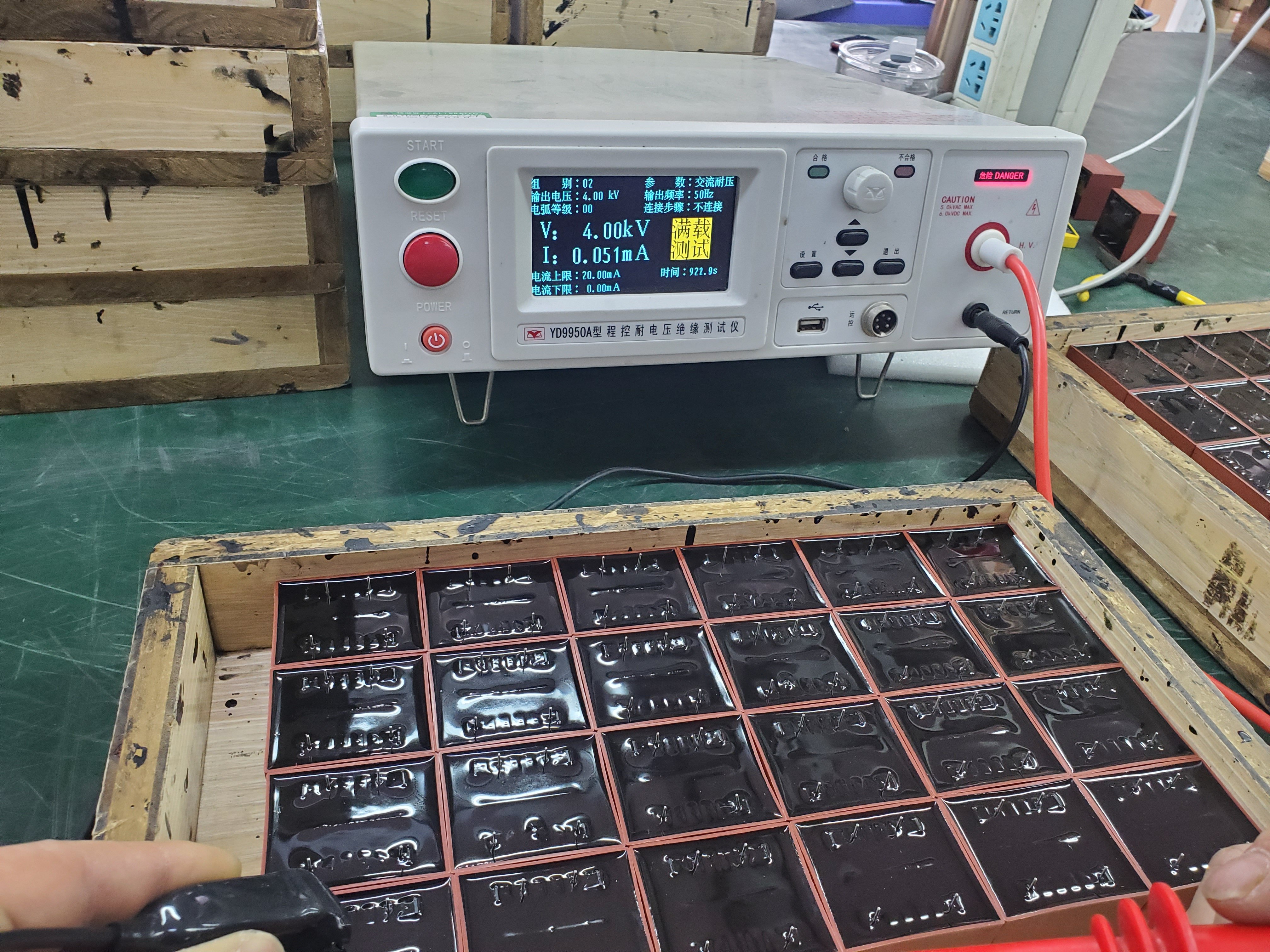
घुमावदार निरंतरता और आउटपुट वोल्टेज से लेकर विद्युत रोधक प्रतिरोध, तापमान वृद्धि और सोल्डर करने की क्षमता तक, ईसीको प्रत्येक पीसीबी ट्रांसफॉर्मर की जाँच अनुमोदित ड्रॉइंग, परीक्षण विनिर्देश और निरीक्षण योजना के अनुसार करता है।
नियमित उत्पादन परीक्षण
|
दृश्य और आयामी निरीक्षण कार्यप्रणाली, लेबल, ध्रुवता के चिह्न, पिन की स्थिति, आकृति के आयाम, बैठी ऊँचाई, पिन के बीच की दूरी और पिन की स्थिति की जाँच अनुमोदित ड्रॉइंग के अनुसार की जाती है। |
वाइंडिंग और आउटपुट सत्यापन वाइंडिंग प्रतिरोध परीक्षण चालक की निरंतरता और उत्पादन स्थिरता की जाँच करता है। टर्न-रेशियो और आउटपुट-वोल्टेज परीक्षण निर्दिष्ट प्राथमिक इनपुट पर आवश्यक द्वितीयक वोल्टेज और वाइंडिंग ध्रुवता की पुष्टि करते हैं। |
नो-लोड और रेटेड-लोड प्रदर्शन नो-लोड धारा और नो-लोड हानि का मूल्यांकन कोर असेंबली, वाइंडिंग स्थिरता और स्टैंडबाय प्रदर्शन की पुष्टि के लिए किया जाता है। परिभाषित इनपुट और लोड स्थितियों के तहत रेटेड-लोड वोल्टेज और विनियमन की पुष्टि की जाती है। |
|
विद्युत रोधक सुरक्षा परीक्षण इन्सुलेशन प्रतिरोध परीक्षण वाइंडिंग्स और पहुँच योग्य चालक भागों के बीच विद्युत अलगाव की जाँच करता है। डाइइलेक्ट्रिक स्ट्रेंथ परीक्षण अनुमोदित वोल्टेज और अवधि पर निर्दिष्ट इन्सुलेशन धारण क्षमता की पुष्टि करता है। |
तापमान वृद्धि और श्रव्य शोर तापमान वृद्धि परीक्षण परिभाषित माउंटिंग, वातावरण और लोड स्थितियों के तहत थर्मल प्रदर्शन की पुष्टि करता है। श्रव्य शोर मूल्यांकन तब किया जाता है जब प्रोजेक्ट विनिर्देश द्वारा ट्रांसफॉर्मर का हम या यांत्रिक कंपन नियंत्रित किया जाता है। |
पीसीबी पिन सॉल्डरेबिलिटी पीसीबी पिन की वेटिंग और सॉल्डरिंग ऊष्मा के प्रति प्रतिरोध का मूल्यांकन किया जाता है ताकि स्थिर पीसीबी असेंबली और दोहराए जा सकने वाले सॉल्डर जॉइंट की गुणवत्ता का समर्थन किया जा सके। |
कस्टम पीसीबी ट्रांसफॉर्मर विकास प्रक्रिया
पीसीबी ट्रांसफॉर्मर अक्सर पूछे जाने वाले प्रश्न
१. पीसीबी ट्रांसफॉर्मर क्या है?
पीसीबी ट्रांसफॉर्मर एक सघन, मुख्य-आवृत्ति वाला ट्रांसफॉर्मर है जिसे मुद्रित परिपथ बोर्ड पर सीधे थ्रू-होल माउंटिंग के लिए डिज़ाइन किया गया है। यह प्राथमिक और द्वितीयक परिपथों के बीच आवश्यक विद्युत अलगाव प्रदान करते हुए इनपुट वोल्टेज को एक या अधिक कम एसी आउटपुट वोल्टेज में परिवर्तित करता है।
२. जब आप कस्टम पीसीबी ट्रांसफॉर्मर के लिए अनुरोध करते हैं, तो आपको कौन-कौन सी जानकारी प्रदान करनी चाहिए?
कृपया इनपुट वोल्टेज और आवृत्ति, प्रत्येक द्वितीयक वोल्टेज और धारा, लोड प्रकार, संचालन ड्यूटी साइकिल, अधिकतम आयाम, पीसीबी फुटप्रिंट, वातावरणीय तापमान, विद्युत रोधन आवश्यकताएँ और अनुमानित वार्षिक मात्रा प्रदान करें। पीसीबी लेआउट, आयामी चित्र या मौजूदा ट्रांसफॉर्मर का नमूना हमारे लिए परियोजना का अधिक सटीक मूल्यांकन करने में सहायता करेगा।
३. पीसीबी ट्रांसफॉर्मर के लिए सही वीए रेटिंग कैसे चुनें?
मूल वीए आवश्यकता की गणना प्रत्येक द्वितीयक वोल्टेज को उसकी नामांकित धारा से गुणा करके और परिणामों को एक साथ जोड़कर की जाती है। रेक्टिफायर सर्किट, धारितात्मक लोड, शिखर धाराएँ, वोल्टेज नियमन की आवश्यकताएँ और उच्च वातावरणीय तापमान के लिए अतिरिक्त डिज़ाइन मार्जिन की आवश्यकता हो सकती है।
4. क्या मुझे द्वितीयक वोल्टेज को नो-लोड या फुल-लोड पर निर्दिष्ट करना चाहिए?
अधिकांश कस्टम परियोजनाओं के लिए, आवश्यक द्वितीयक वोल्टेज को वास्तविक संचालन लोड पर निर्दिष्ट किया जाना चाहिए। कुंडली प्रतिरोध और आंतरिक वोल्टेज ड्रॉप के कारण, ट्रांसफॉर्मर का नो-लोड वोल्टेज सामान्यतः उसके नामांकित लोड वोल्टेज से अधिक होता है। यदि आपके सर्किट में एक कठोर वोल्टेज सीमा है, तो कृपया दोनों मान प्रदान करें।
5. मापा गया नो-लोड वोल्टेज नामांकित आउटपुट वोल्टेज से अधिक क्यों है?
अनुमत द्वितीयक वोल्टेज को सामान्यतः एक निर्दिष्ट लोड पर परिभाषित किया जाता है। जब ट्रांसफॉर्मर बिना किसी लोड के कार्य करता है, तो वाइंडिंग्स के पार लगभग कोई वोल्टेज ड्रॉप नहीं होता है, अतः मापा गया आउटपुट वोल्टेज बढ़ जाता है। नो-लोड और फुल-लोड वोल्टेज के बीच के अंतर को वोल्टेज नियामन कहा जाता है।
6. क्या एक पीसीबी ट्रांसफॉर्मर को ब्रिज रेक्टिफायर और फ़िल्टर कैपेसिटर के लिए डिज़ाइन किया जा सकता है?
हालाँकि, एक रेक्टिफायर-कैपेसिटर इनपुट चिकनी ज्यावक्रीय धारा के बजाय छोटे, उच्च-धारा चार्जिंग पल्स खींचता है। कृपया आवश्यक डीसी आउटपुट वोल्टेज, डीसी लोड धारा, रेक्टिफायर व्यवस्था और फ़िल्टर कैपेसिटैंस के बारे में जानकारी प्रदान करें, ताकि ट्रांसफॉर्मर को वाइंडिंग तापन और वोल्टेज नियामन के लिए सही आकार दिया जा सके।
7. क्या आप पीसीबी का उत्पादन कर सकते हैं ट्रांसफार्मर जिसमें एकाधिक द्वितीयक वाइंडिंग्स हों?
पीसीबी ट्रांसफॉर्मर को एकल, द्विगुणित, केंद्र-टैप्ड या कई स्वतंत्र द्वितीयक वाइंडिंग्स के साथ डिज़ाइन किया जा सकता है। प्रत्येक वाइंडिंग का वोल्टेज, धारा, विद्युत रोधन संबंध और कनेक्शन विधि को मंजूर किए गए विद्युत विनिर्देश में स्पष्ट रूप से परिभाषित किया जाना चाहिए।
8. क्या द्वितीयक वाइंडिंग्स को श्रेणी या समानांतर में जोड़ा जा सकता है?
श्रेणी या समानांतर कनेक्शन के लिए समान द्वितीयक वाइंडिंग्स को डिज़ाइन किया जा सकता है। श्रेणी कनेक्शन उपलब्ध वोल्टेज को बढ़ाता है, जबकि समानांतर कनेक्शन उपलब्ध धारा को बढ़ाता है। सही वाइंडिंग ध्रुवता का पालन करना आवश्यक है, और केवल उन्हीं वाइंडिंग्स को समानांतर में जोड़ा जाना चाहिए जिन्हें विशिष्ट रूप से समान विशेषताओं के साथ डिज़ाइन किया गया हो।
9. क्या आप द्विगुणित 115 वी / 230 वी प्राथमिक वाइंडिंग्स वाला पीसीबी ट्रांसफॉर्मर बना सकते हैं?
दो मेल खाती प्राथमिक वाइंडिंग्स को लगभग 115 वी संचालन के लिए समानांतर में या लगभग 230 वी संचालन के लिए श्रेणी में जोड़ा जा सकता है। आवश्यक कनेक्शन आरेख, पिन असाइनमेंट और सुरक्षा निर्देश मंजूर किए गए ड्रॉइंग पर परिभाषित किए जाएंगे।
10. क्या एक ही पीसीबी ट्रांसफॉर्मर 50 हर्ट्ज़ और 60 हर्ट्ज़ दोनों पर काम कर सकता है?
हाँ, अगर इसे 50/60 हर्ट्ज़ संचालन के लिए डिज़ाइन और रेट किया गया हो। केवल 60 हर्ट्ज़ के लिए डिज़ाइन किया गया ट्रांसफॉर्मर, यदि उसे समान वोल्टेज पर 50 हर्ट्ज़ पर संचालित किया जाए, तो अत्यधिक चुंबकीय फ्लक्स, नो-लोड धारा और तापन का अनुभव कर सकता है। अतः डिज़ाइन की पुष्टि से पहले सबसे कम इरादा किया गया संचालन आवृत्ति बताई जानी चाहिए।