EN
EN

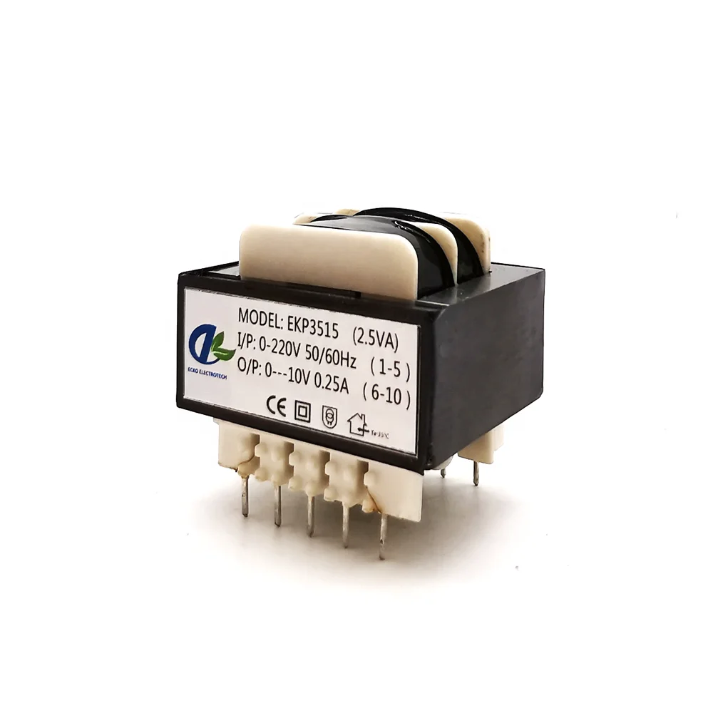
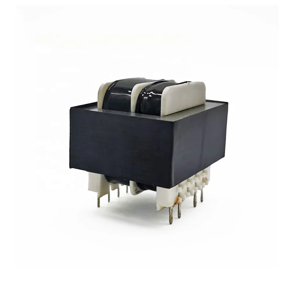
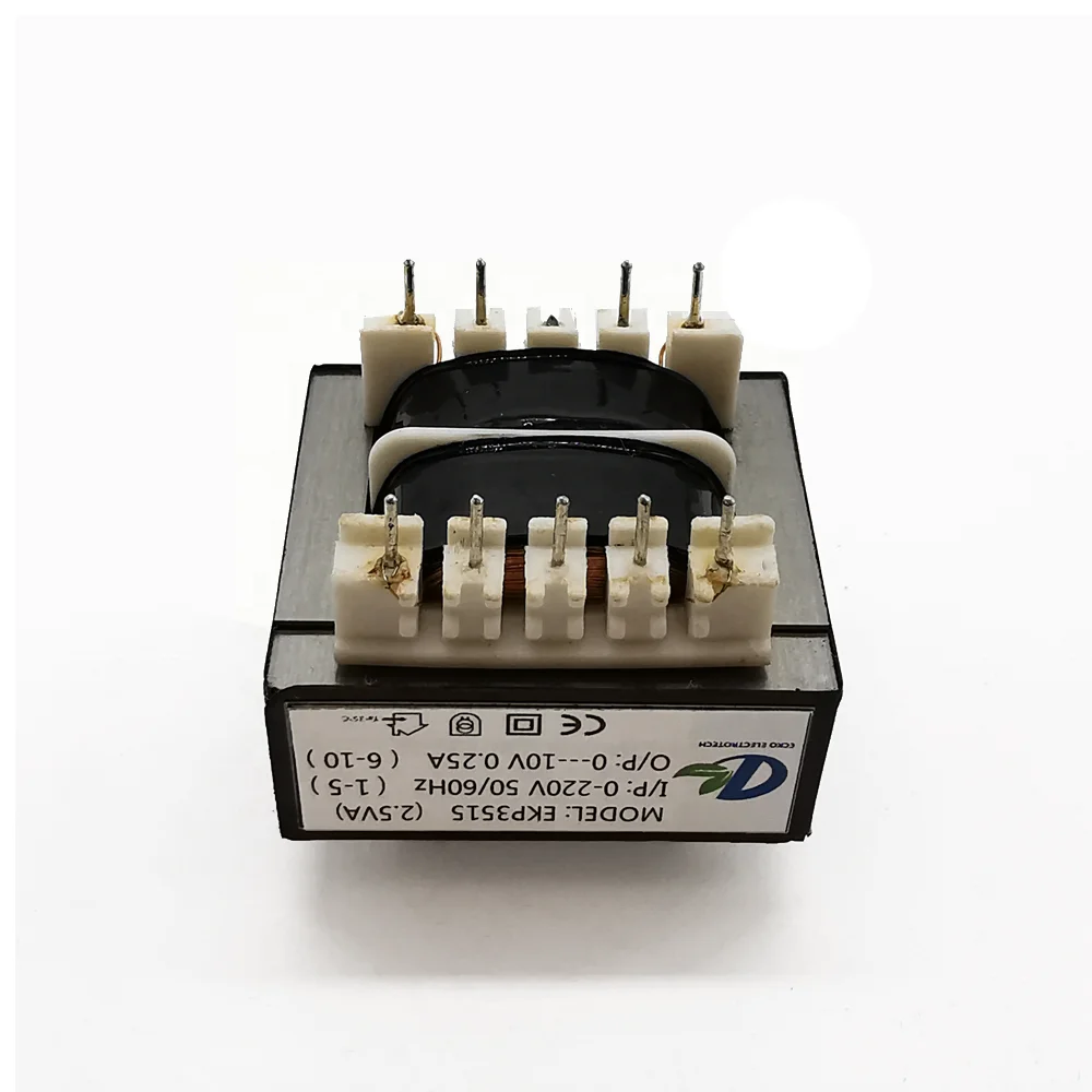
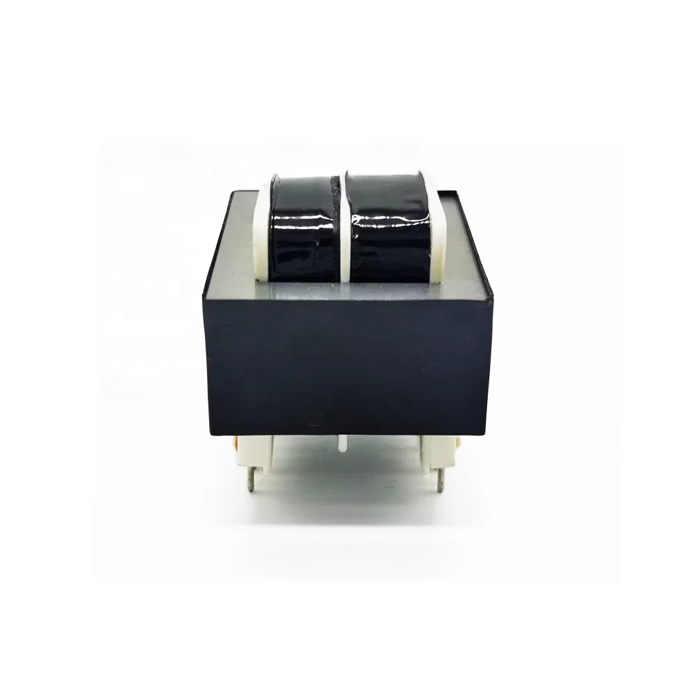
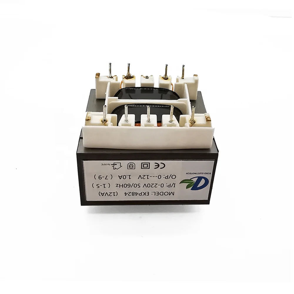
সংক্ষিপ্ত শক্তি সরবরাহ ডিজাইনের জন্য কাস্টম ইআই পিসিবি ট্রান্সফরমার
ওইএম সার্কিট বোর্ডে বিশ্বস্ত একীভূতকরণের জন্য কাস্টমাইজড ইনপুট ভোল্টেজ, আউটপুট ওয়াইন্ডিংস, রেটেড পাওয়ার এবং পিন লেআউট দিয়ে প্রকৌশলীকৃত
| প্যারামিটার | সাধারণ পরিসর / উপলব্ধ বিকল্প |
|---|---|
| পণ্যের ধরন | ওপেন-ফ্রেম, ভ্যাকুয়াম-ইম্প্রিগনেটেড অথবা সম্পূর্ণ এনক্যাপসুলেটেড পিসিবি ট্রান্সফর্মার |
| রেটেড পাওয়ার | সাধারণত ০.৫ ভিএ থেকে ৩০ ভিএ; উচ্চ রেটিংয়ের ক্ষেত্রে প্রকৌশলী পর্যালোচনা প্রয়োজন |
| প্রাথমিক ভোল্টেজ | ১০০ ভোল্ট, ১১০ ভোল্ট, ১১৫ ভোল্ট, ১২০ ভোল্ট, ২০০ ভোল্ট, ২২০ ভোল্ট, ২৩০ ভোল্ট অথবা ২৪০ ভোল্ট এসি; একক অথবা দ্বৈত প্রাইমারি |
| বাহুল্য ভোল্টেজ | প্রতিটি ওয়াইন্ডিংয়ে সাধারণত ৩ ভোল্ট থেকে ৪৮ ভোল্ট এসি; অন্যান্য ভোল্টেজ উপলব্ধ |
| আউটপুট কনফিগারেশন | একক, সেন্টার-ট্যাপড, দ্বৈত অথবা বহু সেকেন্ডারি ওয়াইন্ডিং |
| ফ্রিকোয়েন্সি | 50Hz, 60Hz অথবা 50/60Hz |
| কেন্দ্রীয় উপাদান | শক্তি এবং তাপমাত্রা-বৃদ্ধির প্রয়োজন অনুযায়ী নির্বাচিত ইআই ল্যামিনেটেড বৈদ্যুতিক ইস্পাত কোর |
| ফুটোয়ারা উপাদান | তামা চালক তার |
| আইসোলেশন ক্লাস | ক্লাস বি ১৩০°সে অথবা ক্লাস এফ ১৫৫°সে |
| ডায়েলক্ট্রিক শক্তি | প্রকল্প-নির্দিষ্ট; ৩.০–৪.০ কেভিএসি প্রাইমারি-টু-সেকেন্ডারি বিকল্পগুলি সাধারণত পাওয়া যায় |
| তাপমাত্রা বৃদ্ধি | নির্ধারিত লোড, পরিবেশগত তাপমাত্রা, আবদ্ধক এবং অ্যান্টিসিপেশন শ্রেণি অনুযায়ী সংজ্ঞায়িত |
| মাউন্ট পদ্ধতি | থ্রু-হোল পিসিবি পিন |
| পিন কনফিগারেশন | কাস্টম পিন সংখ্যা, পিচ, সারি ব্যবধান, ব্যাস, দৈর্ঘ্য এবং পোলারিটি মার্কিং |
| সুরক্ষা বিকল্পসমূহ | তাপীয় ফিউজ, রিসেটেবল তাপীয় প্রোটেক্টর অথবা বহিঃস্থ পিটিসি সমন্বয় |
| শিল্ডিং বিকল্প | ইলেকট্রোস্ট্যাটিক শিল্ড, ইন্টার-উইন্ডিং শিল্ড অথবা প্রয়োজনীয় স্থানে চৌম্বকীয় শিল্ডিং |
| চালু তাপমাত্রা | সাধারণ ডিজাইন পরিসর -২০°সে থেকে +৭০°সে, উপকরণ সিস্টেমের উপর নির্ভর করে |
| অনুগতি বিকল্প | নির্মাণ প্রযোজ্য আইইসি, ইএন অথবা ইউএল প্রয়োজনীয়তার জন্য ডিজাইন করা হয়েছে; অনুমোদন মডেল-নির্দিষ্ট |
- সংক্ষিপ্ত বিবরণ
- সুপারিশকৃত পণ্য
- চোখের পরীক্ষা: নিয়মিত বা নমুনা পরীক্ষা
- মাত্রাগত পরীক্ষা: নমুনা গ্রহণ, যেখানে গুরুত্বপূর্ণ মাত্রাগুলি নির্দিষ্ট অনুযায়ী নিয়ন্ত্রণ করা হয়
- কুণ্ডলী রোধ: নিয়মিত পরীক্ষা
- টার্নস রেশিও / আউটপুট ভোল্টেজ: ১০০% নিয়মিত পরীক্ষা
- অ-লোড কারেন্ট: ১০০% অথবা চুক্তিবদ্ধ পরীক্ষা পরিকল্পনা
- নো-লোড লস: নমুনা পরীক্ষা অথবা যোগ্যতা পরীক্ষা
- লোড ভোল্টেজ ও রেগুলেশন: নমুনা এবং পর্যায়ক্রমিক যাচাই
- আইসুলেশন রিজিস্টেন্স: নিয়মিত বা নমুনা পরীক্ষা
- ডাই-ইলেকট্রিক স্ট্রেংথ / হাই-পট: অনুমোদিত পরীক্ষা স্তরে ১০০%
- তাপমাত্রা বৃদ্ধি: প্রকার বা যোগ্যতা পরীক্ষা
- শোনা যাওয়া শব্দ: যখন অনুমোদিত স্পেসিফিকেশন দ্বারা প্রয়োজন হয়
- সোল্ডারযোগ্যতা: যোগ্যতা বা নমুনা পরীক্ষা
- সোল্ডারিংয়ের তাপ প্রতিরোধের ক্ষমতা: প্রকল্পের প্রয়োজনীয়তা অনুযায়ী যাচাই করা হয়েছে
আপনার সার্কিট বোর্ডের জন্য প্রকৌশলীদের দ্বারা কাস্টমাইজড পিসিবি ট্রান্সফর্মার
সংক্ষিপ্ত থ্রু-হোল পিসিবি ট্রান্সফরমার যার ইনপুট ভোল্টেজ, আউটপুট ওয়াইন্ডিংস, রেটেড পাওয়ার, পিন লেআউট এবং ইনসুলেশন কনস্ট্রাকশন কাস্টমাইজ করা যায়। ইকো প্রতিটি ট্রান্সফরমার আপনার লোড প্রয়োজনীয়তা, পিসিবি ফুটপ্রিন্ট, তাপমাত্রা বৃদ্ধির লক্ষ্য এবং প্রযোজ্য নিরাপত্তা প্রয়োজনীয়তা অনুযায়ী ডিজাইন করে।
প্রাথমিক বৈদ্যুতিক গণনা থেকে অনুমোদিত আঁকা, নিয়ন্ত্রিত উৎপাদন এবং নিয়মিত বৈদ্যুতিক পরীক্ষা পর্যন্ত, আমরা ওইইম গ্রাহকদের তাদের পিসিবি অ্যাসেম্বলিতে বিশ্বস্ত মেইন-ফ্রিকোয়েন্সি পাওয়ার কনভার্শন সরাসরি একীভূত করতে সাহায্য করি।
সাধারণ পিসিবি ট্রান্সফর্মার বিশেষৈষ্ট্য
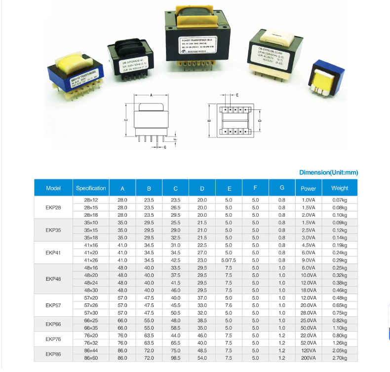
বিশেষকরণ বিজ্ঞপ্তি: উপরের মানগুলি একটি নির্দিষ্ট ক্যাটালগ মডেলের চেয়ে বরং সাধারণ প্রকৌশল ক্ষমতার প্রতিনিধিত্ব করে। চূড়ান্ত বৈদ্যুতিক রেটিং, মাত্রা, সহনশীলতা এবং পরীক্ষার সীমা গ্রাহক-অনুমোদিত বিশেষকরণ এবং মাত্রা আঁকার দ্বারা নির্ধারিত হয়।
পিসিবি ট্রান্সফরমার পণ্যের সুবিধাসমূহ
পিসিবি ট্রান্সফরমার কাস্টমাইজেশন অপশন
|
বৈদ্যুতিক ইনপুট |
বৈদ্যুতিক আউটপুট |
রেটেড পাওয়ার |
পিসিবি ফুটপ্রিন্ট |
|
পণ্যের মাত্রা |
ইনসুলেশন সিস্টেম |
ডায়েলক্ট্রিক শক্তি |
তাপীয় সুরক্ষা |
|
পরিবেশ রক্ষার জন্য |
শব্দ নিয়ন্ত্রণ |
নথিপত্র |
প্যাকেজিং |












কেন কাস্টম পিসিবি ট্রান্সফরমারের জন্য ইকো বেছে নেবেন?
পিসিবি ট্রান্সফর্মার পরীক্ষা এবং রেফারেন্স মানদণ্ড
ইসিকেও প্রতিটি পিসিবি ট্রান্সফরমার অনুমোদিত ড্রয়িং, পরীক্ষা বিবরণ এবং পরিদর্শন পরিকল্পনা অনুযায়ী পাকানো অবিরততা ও আউটপুট ভোল্টেজ থেকে ইনসুলেশন ধারণ ক্ষমতা, তাপমাত্রা বৃদ্ধি এবং সোল্ডারযোগ্যতা পর্যন্ত যাচাই করে।
নিয়মিত উৎপাদন পরীক্ষা
|
দৃশ্য এবং আকৃতি পরিমাপের পরীক্ষা অনুমোদিত ড্রয়িং অনুযায়ী কাজের মান, লেবেল, মেরুতা চিহ্ন, পিনের অবস্থা, আকৃতির মাত্রা, সিটড উচ্চতা, পিন পিচ এবং পিনের অবস্থান পরীক্ষা করা হয়। |
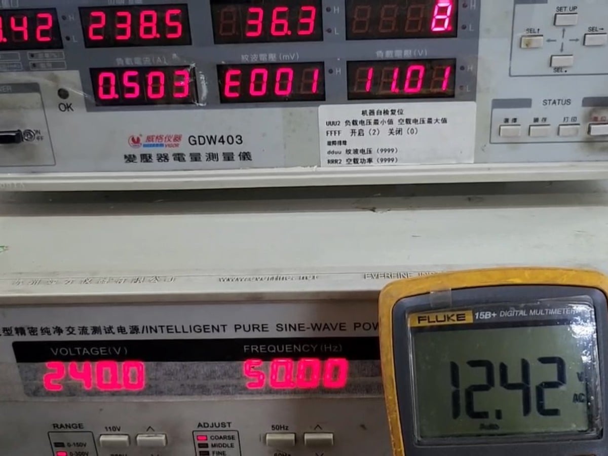
পাকানো ও আউটপুট যাচাই পাকানো রেজিস্ট্যান্স পরীক্ষা পরিবাহীর অবিরততা এবং উৎপাদনের সামঞ্জস্যতা যাচাই করে। টার্নস-রেশিও ও আউটপুট-ভোল্টেজ পরীক্ষা নির্দিষ্ট প্রাইমারি ইনপুটে প্রয়োজনীয় সেকেন্ডারি ভোল্টেজ ও পাকানোর মেরুতা নিশ্চিত করে। |
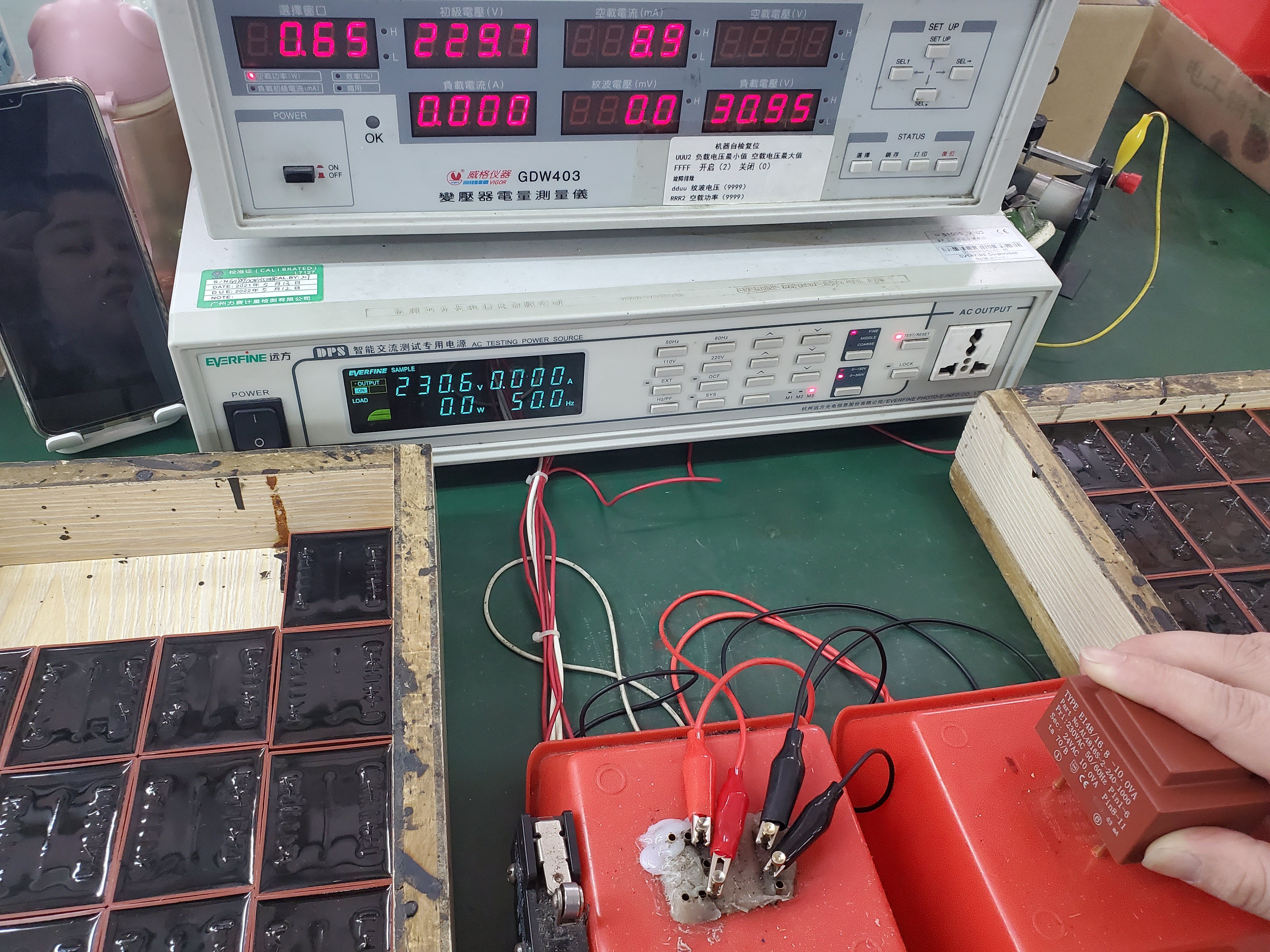
নো-লোড ও রেটেড-লোড পারফরম্যান্স নো-লোড কারেন্ট ও নো-লোড লস মূল্যায়ন করা হয় কোর অ্যাসেম্বলি, পাকানোর সামঞ্জস্যতা এবং স্ট্যান্ডবাই পারফরম্যান্স নিশ্চিত করতে। নির্দিষ্ট ইনপুট ও লোড শর্তে রেটেড-লোড ভোল্টেজ ও রেগুলেশন যাচাই করা হয়। |
|
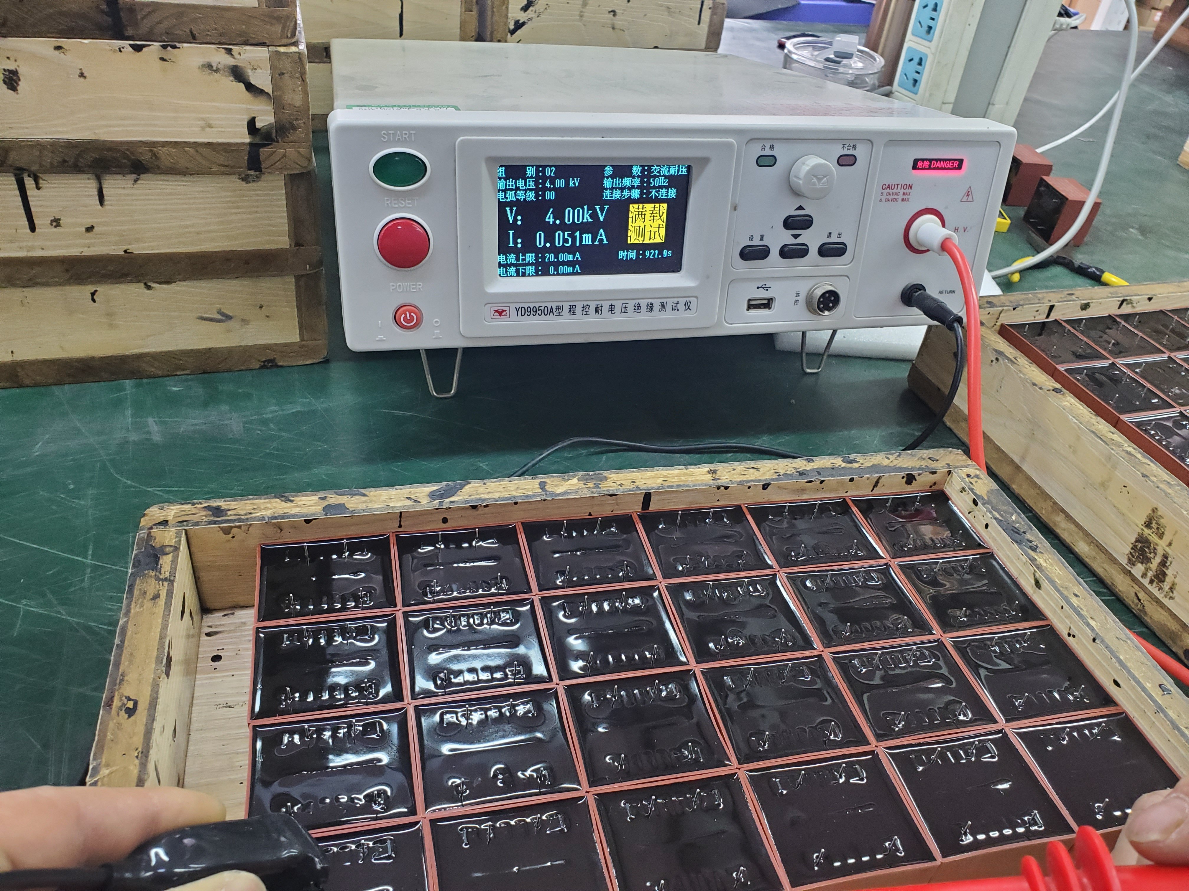
ইনসুলেশন নিরাপত্তা পরীক্ষা ইনসুলেশন রেজিস্ট্যান্স পরীক্ষা কয়েল এবং অ্যাক্সেসযোগ্য কন্ডাক্টিভ অংশের মধ্যে বৈদ্যুতিক বিচ্ছিন্নতা পরীক্ষা করে। ডাই-ইলেকট্রিক স্ট্রেংথ পরীক্ষা অনুমোদিত ভোল্টেজ ও সময়ের মধ্যে নির্দিষ্ট ইনসুলেশন সহ্য ক্ষমতা যাচাই করে। |
তাপমাত্রা বৃদ্ধি এবং শোনা যাওয়া শব্দ তাপমাত্রা বৃদ্ধি পরীক্ষা নির্দিষ্ট মাউন্টিং, পরিবেশগত এবং লোড শর্তে তাপীয় কার্যকারিতা যাচাই করে। ট্রান্সফরমারের হাম বা যান্ত্রিক কম্পন প্রকল্পের স্পেসিফিকেশন দ্বারা নিয়ন্ত্রিত হলে শোনা যাওয়া শব্দ মূল্যায়ন করা হয়। |
পিসিবি পিন সোল্ডারযোগ্যতা পিসিবি পিনের ওয়েটিং এবং সোল্ডারিংয়ের তাপ প্রতিরোধের মূল্যায়ন করা হয় যাতে স্থিতিশীল পিসিবি অ্যাসেম্বলি এবং পুনরাবৃত্তিযোগ্য সোল্ডার জয়েন্ট গুণগত মান সমর্থন করা যায়। |
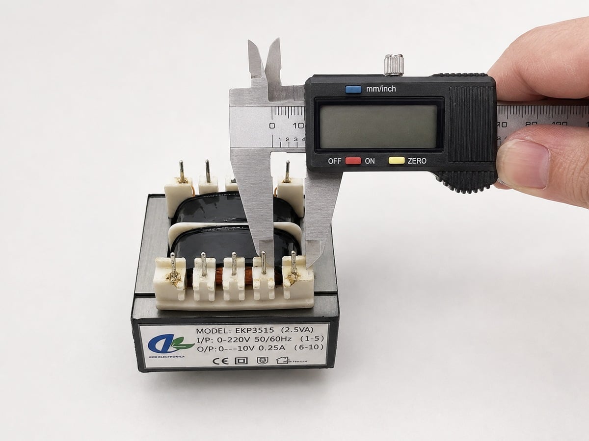
কাস্টম পিসিবি ট্রান্সফরমার ডেভেলপমেন্ট প্রক্রিয়া
পিসিবি ট্রান্সফর্মার সম্পর্কিত প্রশ্নোত্তর
১. পিসিবি ট্রান্সফরমার কী?
একটি পিসিবি ট্রান্সফরমার হলো একটি কমপ্যাক্ট, মেইনস-ফ্রিক uয়েন্সি ট্রান্সফরমার যা প্রিন্টেড সার্কিট বোর্ডে সরাসরি থ্রু-হোল মাউন্টিংয়ের জন্য ডিজাইন করা হয়েছে। এটি ইনপুট ভোল্টেজকে এক বা একাধিক নিম্ন-এসি আউটপুট ভোল্টেজে রূপান্তর করে এবং প্রাইমারি ও সেকেন্ডারি সার্কিটের মধ্যে প্রয়োজনীয় বৈদ্যুতিক আইসোলেশন প্রদান করে।
৩. কাস্টম পিসিবি ট্রান্সফরমার অর্ডার করার সময় আমাকে কোন তথ্যগুলি প্রদান করতে হবে?
অনুগ্রহ করে ইনপুট ভোল্টেজ ও ফ্রিকুয়েন্সি, প্রতিটি সেকেন্ডারি ভোল্টেজ ও কারেন্ট, লোড টাইপ, অপারেটিং ডিউটি সাইকেল, সর্বোচ্চ মাত্রা, পিসিবি ফুটপ্রিন্ট, পরিবেশগত তাপমাত্রা, ইনসুলেশন প্রয়োজনীয়তা এবং আনুমানিক বার্ষিক পরিমাণ প্রদান করুন। একটি পিসিবি লেআউট, মাত্রা অঙ্কন বা বিদ্যমান ট্রান্সফরমার নমুনা প্রকল্পটি আরও সঠিকভাবে মূল্যায়ন করতে আমাদের সহায়তা করবে।
৩. কীভাবে একটি পিসিবি ট্রান্সফরমারের জন্য সঠিক ভিএ রেটিং নির্বাচন করবেন?
মৌলিক ভ্যাপার-অ্যাম্পিয়ার (ভিএ) প্রয়োজনীয়তা গণনা করা হয় প্রতিটি সেকেন্ডারি ভোল্টেজকে তার নামমাত্র কারেন্ট দিয়ে গুণ করে এবং ফলাফলগুলো যোগ করে। রেকটিফায়ার সার্কিট, ক্যাপাসিটিভ লোড, পিক কারেন্ট, ভোল্টেজ রেগুলেশন প্রয়োজন এবং উচ্চ পরিবেশগত তাপমাত্রার জন্য অতিরিক্ত ডিজাইন মার্জিন প্রয়োজন হতে পারে।
৪. আমি কি সেকেন্ডারি ভোল্টেজ নো-লোড অবস্থায় না ফুল-লোড অবস্থায় নির্দিষ্ট করব?
অধিকাংশ কাস্টম প্রজেক্টের জন্য, প্রয়োজনীয় সেকেন্ডারি ভোল্টেজ আসল অপারেটিং লোডে নির্দিষ্ট করা উচিত। একটি ট্রান্সফরমারের নো-লোড ভোল্টেজ সাধারণত তার নামমাত্র লোড ভোল্টেজের চেয়ে বেশি হয়, কারণ ওয়াইন্ডিংয়ের রেজিস্ট্যান্স এবং অভ্যন্তরীণ ভোল্টেজ ড্রপের কারণে। আপনার সার্কিটে যদি কঠোর ভোল্টেজ রেঞ্জ থাকে, তবে দুটো মানই দিন।
৫. মাপা নো-লোড ভোল্টেজ নামমাত্র আউটপুট ভোল্টেজের চেয়ে বেশি হয় কেন?
মান দেওয়া দ্বিতীয়ক ভোল্টেজটি সাধারণত একটি নির্দিষ্ট লোডে সংজ্ঞায়িত করা হয়। যখন ট্রান্সফরমারটি কোনো লোড ছাড়াই কাজ করে, তখন ওয়াইন্ডিংগুলির মধ্যে প্রায় কোনো ভোল্টেজ ড্রপ হয় না, ফলে পরিমাপ করা আউটপুট ভোল্টেজ বৃদ্ধি পায়। নো-লোড এবং ফুল-লোড ভোল্টেজের মধ্যে পার্থক্যটিকে ভোল্টেজ রেগুলেশন বলা হয়।
৬. কি একটি পিসিবি ট্রান্সফরমার ব্রিজ রেকটিফায়ার এবং ফিল্টার ক্যাপাসিটারের জন্য ডিজাইন করা যেতে পারে?
তবে, রেকটিফায়ার-ক্যাপাসিটার ইনপুট চিকন সাইনোসয়েডাল কারেন্টের পরিবর্তে সংক্ষিপ্ত, উচ্চ-কারেন্ট চার্জিং পালস টানে। অনুগ্রহ করে প্রয়োজনীয় ডিসি আউটপুট ভোল্টেজ, ডিসি লোড কারেন্ট, রেকটিফায়ার বিন্যাস এবং ফিল্টার ক্যাপাসিট্যান্স সরবরাহ করুন, যাতে ওয়াইন্ডিংয়ের তাপ উৎপাদন এবং ভোল্টেজ রেগুলেশনের জন্য ট্রান্সফরমারটি সঠিকভাবে আকার নির্ধারণ করা যায়।
৭. আপনি কি পিসিবি ট্রান্সফরমার বহু দ্বিতীয়ক ওয়াইন্ডিং সহ তৈরি করতে পারেন?
পিসিবি ট্রান্সফরমারটি একক, ডুয়াল, সেন্টার-ট্যাপড বা একাধিক স্বাধীন সেকেন্ডারি ওয়াইন্ডিং দিয়ে ডিজাইন করা যেতে পারে। প্রতিটি ওয়াইন্ডিং-এর ভোল্টেজ, কারেন্ট, ইনসুলেশন সম্পর্ক এবং সংযোগ পদ্ধতি অনুমোদিত বৈদ্যুতিক স্পেসিফিকেশনে স্পষ্টভাবে সংজ্ঞায়িত করা উচিত।
৮. সেকেন্ডারি ওয়াইন্ডিংগুলি শ্রেণিবদ্ধ বা সমান্তরালভাবে সংযুক্ত করা যাবে?
শ্রেণিবদ্ধ বা সমান্তরাল সংযোগের জন্য অভিন্ন সেকেন্ডারি ওয়াইন্ডিং ডিজাইন করা যেতে পারে। শ্রেণিবদ্ধ সংযোগ উপলব্ধ ভোল্টেজ বৃদ্ধি করে, আর সমান্তরাল সংযোগ উপলব্ধ কারেন্ট বৃদ্ধি করে। সঠিক ওয়াইন্ডিং পোলারিটি অবশ্যই মেনে চলতে হবে, এবং শুধুমাত্র সুনির্দিষ্টভাবে মিলে যাওয়া বৈশিষ্ট্য সহ ডিজাইন করা ওয়াইন্ডিংগুলিই সমান্তরালভাবে সংযুক্ত করা যাবে।
৯. আপনি কি ডুয়াল ১১৫ ভোল্ট/২৩০ ভোল্ট প্রাইমারি ওয়াইন্ডিং সহ একটি পিসিবি ট্রান্সফরমার তৈরি করতে পারেন?
দুটি মিলে যাওয়া প্রাইমারি ওয়াইন্ডিং প্রায় ১১৫ ভোল্ট অপারেশনের জন্য সমান্তরালভাবে বা প্রায় ২৩০ ভোল্ট অপারেশনের জন্য শ্রেণিবদ্ধভাবে সংযুক্ত করা যেতে পারে। প্রয়োজনীয় সংযোগ ডায়াগ্রাম, পিন অ্যাসাইনমেন্ট এবং নিরাপত্তা নির্দেশাবলী অনুমোদিত ড্রয়িং-এ সংজ্ঞায়িত করা হবে।
১০. একই পিসিবি ট্রান্সফরমার ৫০ হার্জ এবং ৬০ হার্জ উভয় ফ্রিক uয়েন্সিতে কাজ করতে পারে?
হ্যাঁ, যদি এটি ৫০/৬০ হার্জ অপারেশনের জন্য ডিজাইন করা হয়ে থাকে এবং সেই অনুযায়ী রেটেড হয়ে থাকে। শুধুমাত্র ৬০ হার্জের জন্য ডিজাইন করা একটি ট্রান্সফরমার যদি একই ভোল্টেজে ৫০ হার্জে চালানো হয়, তবে এটি অতিরিক্ত চৌম্বকীয় ফ্লাক্স, নো-লোড কারেন্ট এবং তাপ উৎপন্ন করতে পারে। সুতরাং ডিজাইন অনুমোদনের আগে ন্যূনতম নির্দিষ্ট অপারেটিং ফ্রিকুয়েন্সি উল্লেখ করা আবশ্যিক।