EN
EN

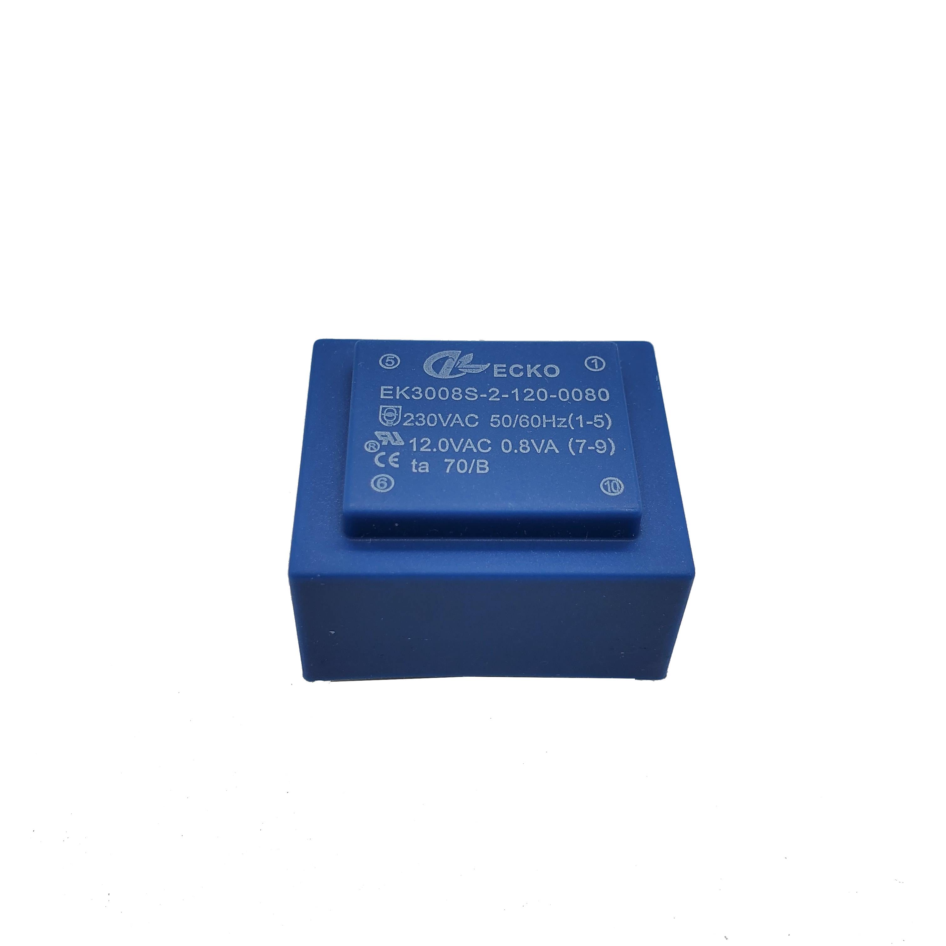
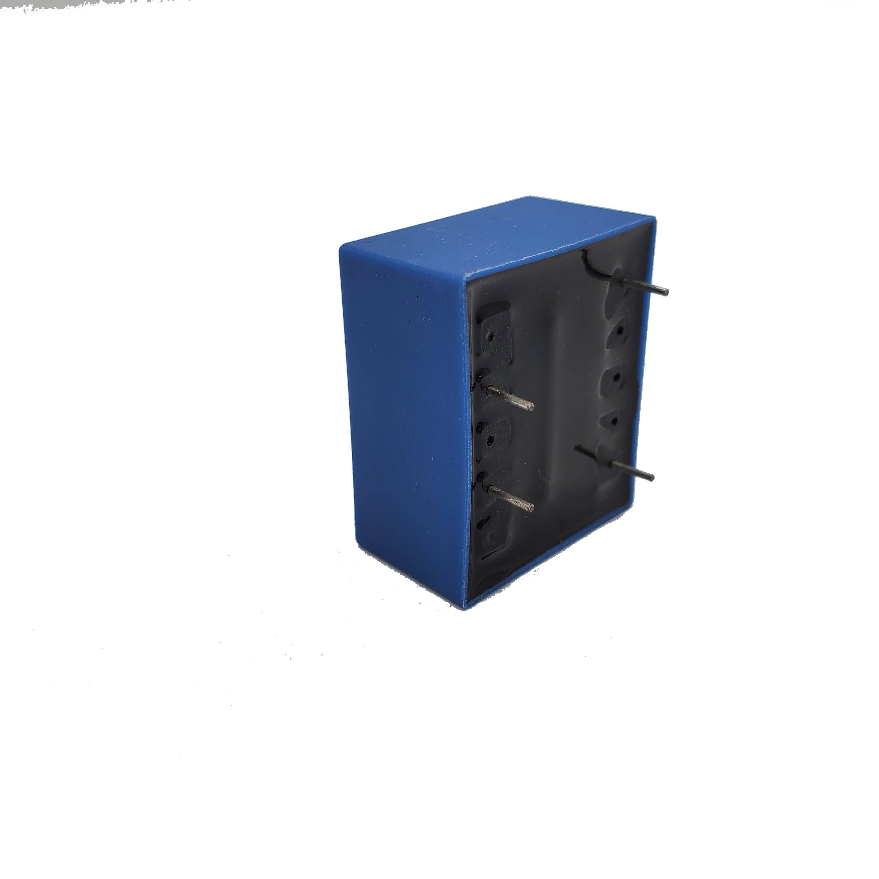
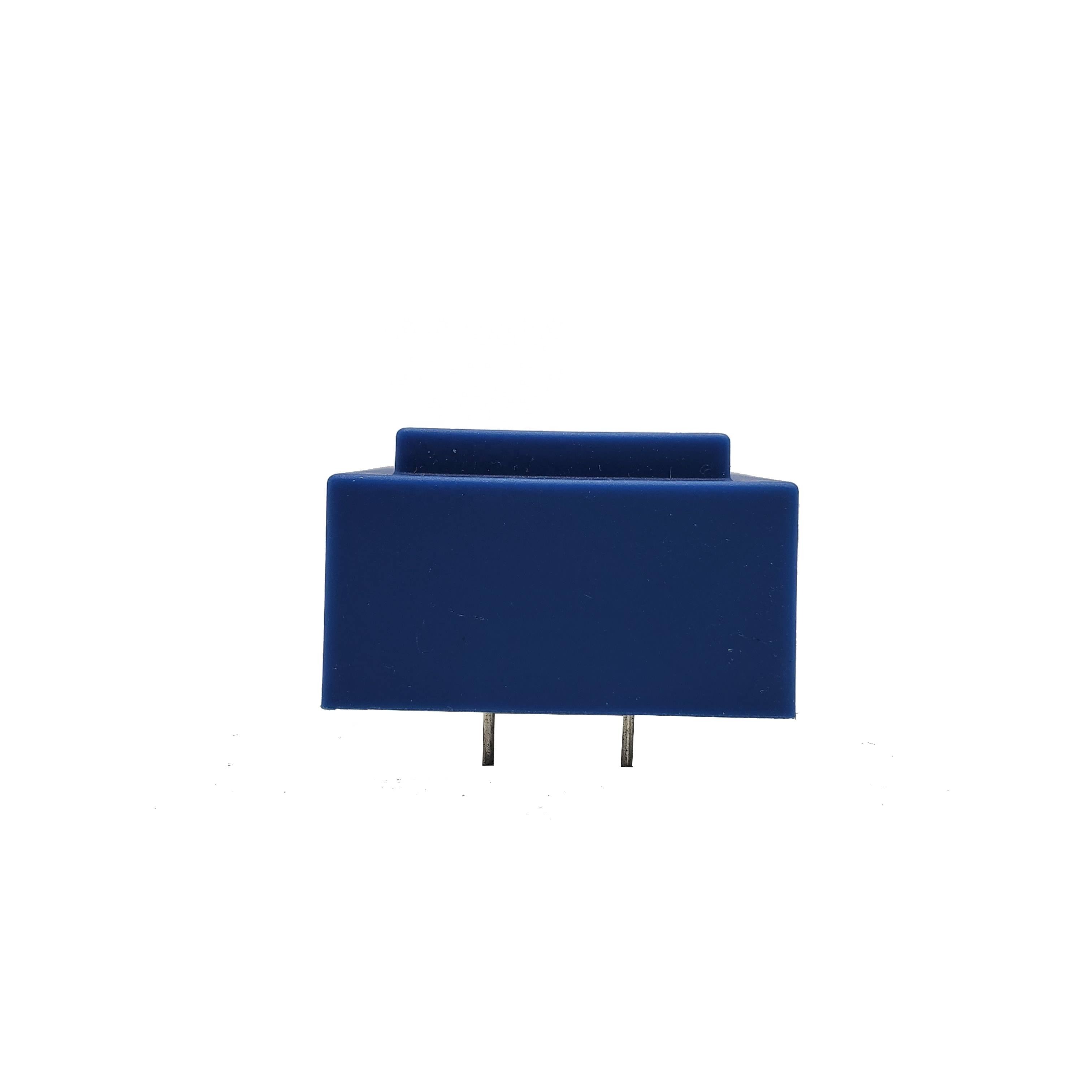
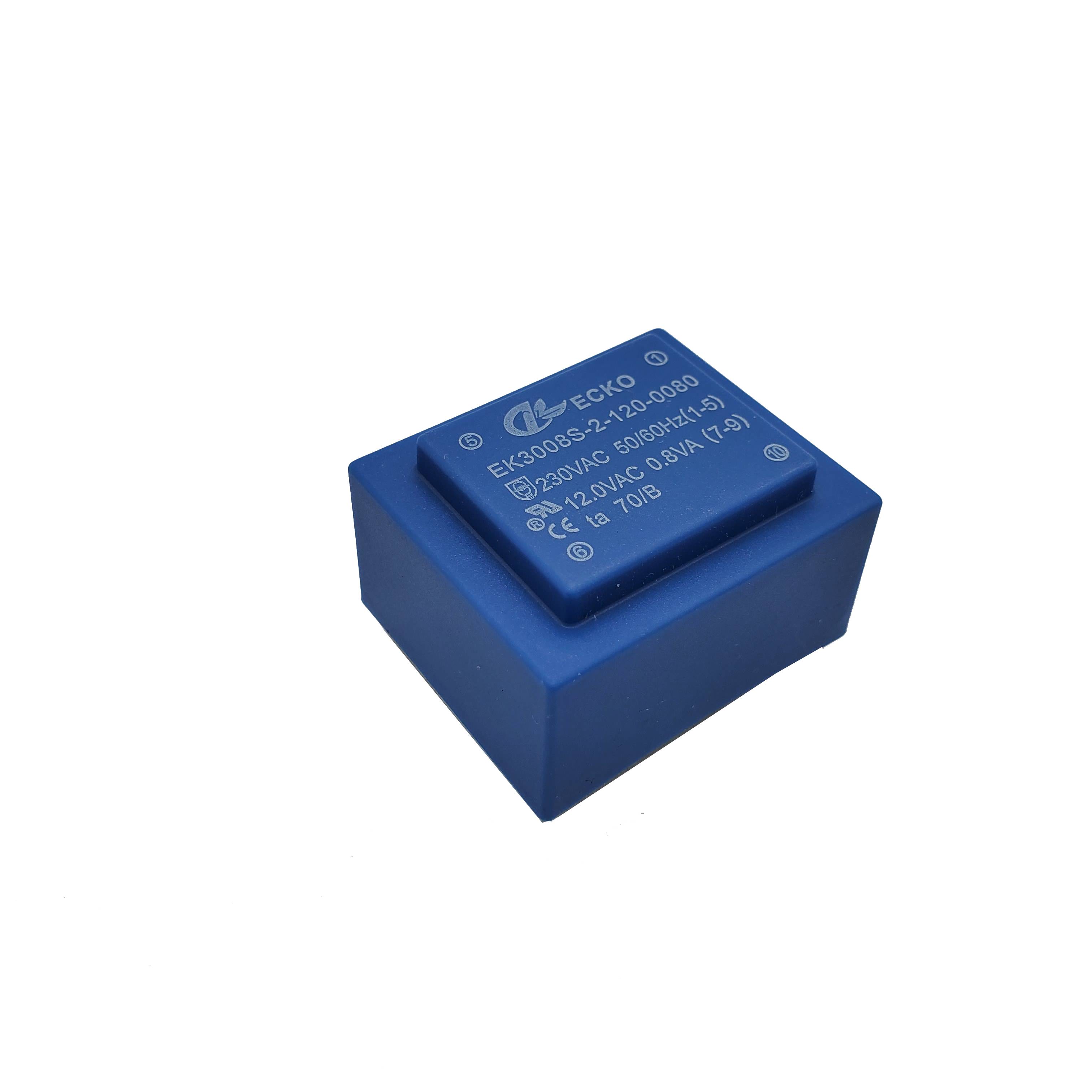
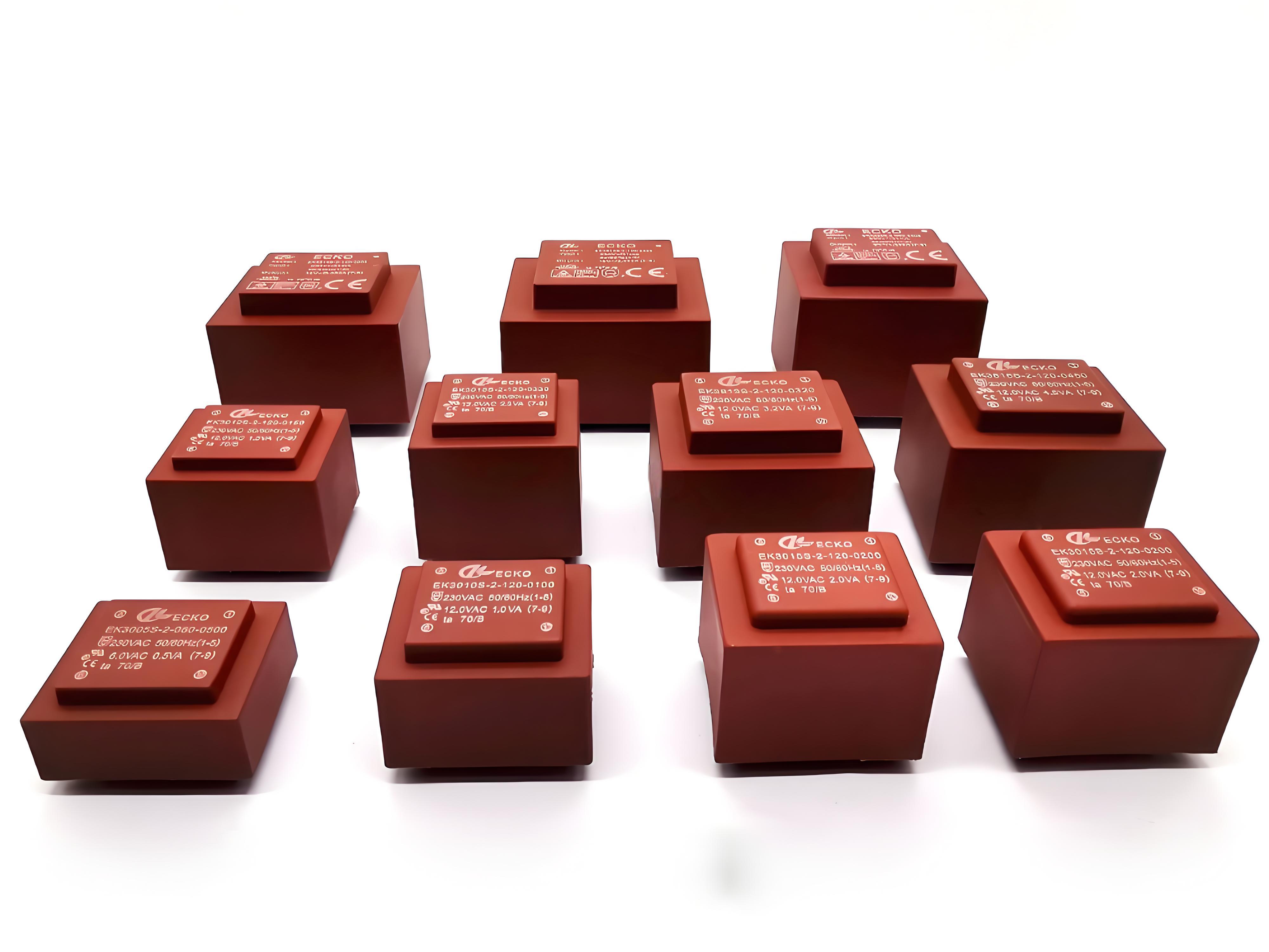
230V to 12V Encapsulated PCB Transformer for Control Circuit Power Supply
Reliable PCB-mounted step-down transformer with encapsulated construction for control boards, automation equipment, instrumentation and low-voltage electronic circuits.
- Overview
- Recommended Products
Encapsulated PCB Transformer Specifications
| Parameter | Typical Range / Available Options |
|---|---|
| Product Type | Low-frequency encapsulated PCB-mount transformer |
| Construction | EI laminated core, copper windings, insulated bobbin, protective enclosure and resin encapsulation |
| Rated Power | Typically 0.5 VA to 60 VA; other ratings subject to engineering review |
| Primary Voltage | 100 V, 110 V, 115 V, 120 V, 127 V, 200 V, 208 V, 220 V, 230 V or 240 V AC |
| Dual Primary Options | 2 × 115 V, 2 × 120 V or other series/parallel configurations |
| Secondary Voltage | Typically 3 V to 48 V AC; custom voltage available |
| Secondary Configuration | Single, dual, center-tapped or multiple independent windings |
| Frequency | 50 Hz, 60 Hz or 50/60 Hz |
| Output Type | Isolated AC output |
| Core Material | Laminated electrical steel selected according to power, loss and temperature-rise requirements |
| Winding Material | Specified-grade enameled copper wire |
| Dielectric Strength | Commonly designed within a 3,000–4,000 VAC range; final voltage and test duration depend on the approved insulation system and applicable standard |
| Insulation Resistance | Commonly ≥100 MΩ at 500 V DC; final acceptance criteria according to the approved specification |
| Insulation Class | Class B 130°C or Class F 155°C options |
| Temperature Rise | Defined according to rated load, ambient temperature, enclosure condition and applicable standard |
| Voltage Regulation | Optimized according to output voltage, load current, size and temperature-rise requirements |
| Encapsulation | Flame-retardant epoxy or other resin system selected according to project requirements |
| Housing | Standard or custom molded enclosure; flame-retardant material options available |
| Mounting | Through-hole PCB mounting |
| Pin Layout | Standard or fully customized pin spacing and pin assignment |
| Protection Options | Thermal fuse, PTC protection, current-limiting design or short-circuit-resistant design where required |
| Shielding Options | Electrostatic shield between primary and secondary windings |
| Compliance Options | IEC/EN 61558, UL 5085, CE, UL/cUL, RoHS and REACH requirements, subject to model and project scope |
| Marking | Model number, electrical rating, date code, batch code, customer logo or private label |
| Packaging | Individual partitions, trays, cartons and export pallets |
The values above represent common design options rather than the guaranteed specification of every model. Final electrical ratings, dimensions, test limits and compliance requirements are defined in the ECKO-approved product specification and dimensional drawing.
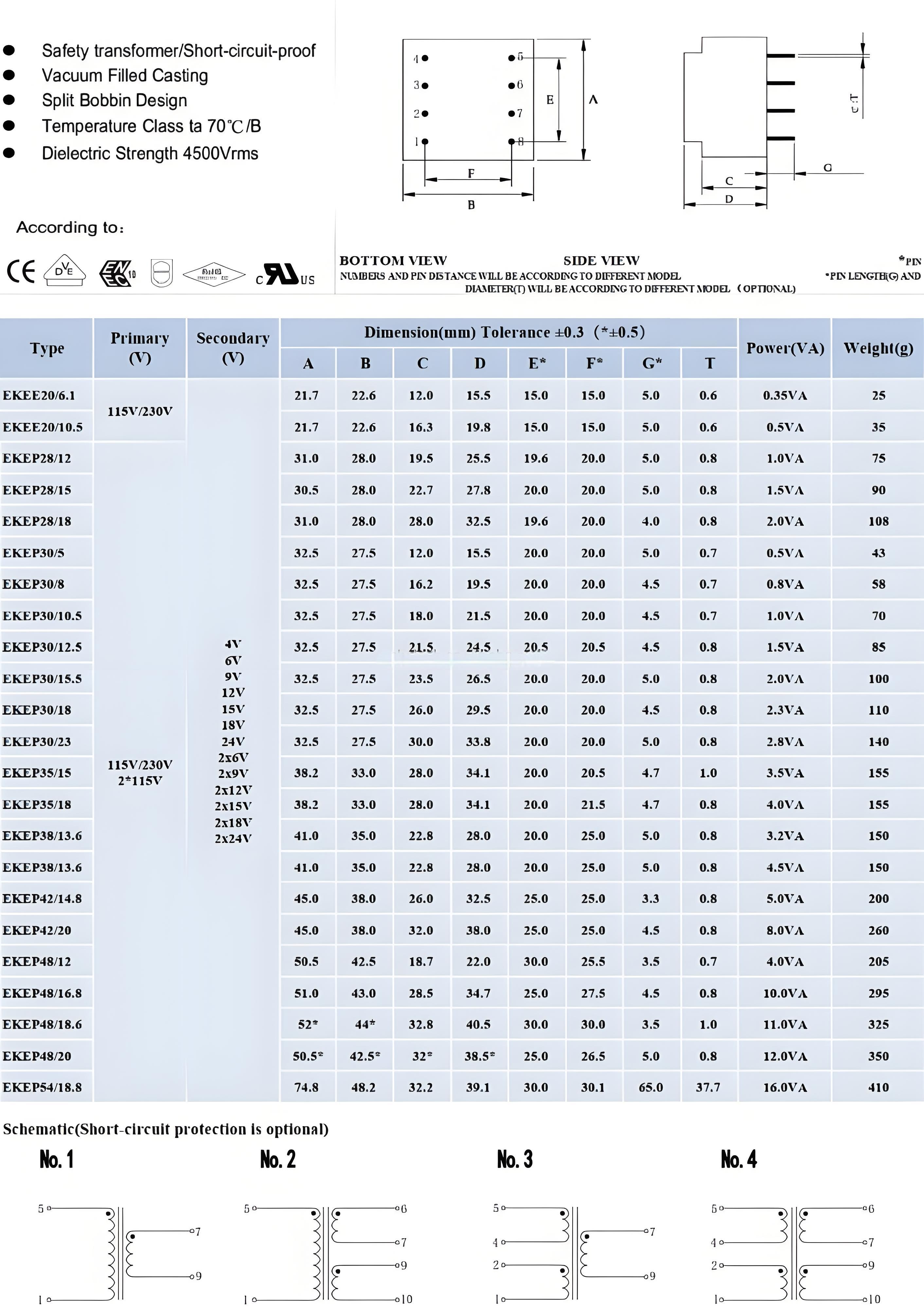
Key Advantages of ECKO Encapsulated PCB Transformers
Custom Encapsulated PCB Transformer Options
Encapsulated PCB Transformer Applications
ECKO encapsulated PCB transformer provide compact AC voltage conversion and electrical isolation for industrial, commercial and consumer electronic assemblies. Each transformer can be customized around the PCB footprint, load profile, operating temperature and safety requirements of the end product.
Why Choose ECKO as Your Encapsulated PCB Transformer Manufacturer?
Engineering Design Based on Your Actual Application
Testing Items and Acceptance Standards
| Test Item | Purpose | Inspection Frequency | Acceptance Basis |
| Visual Inspection | Checks housing, resin surface, marking, pins and workmanship | 100% | Approved appearance criteria and workmanship standard |
| Dimensions and Pin Alignment | Confirms PCB fit and mechanical tolerances | According to control plan | Approved dimensional drawing |
| Winding Continuity | Detects open circuits and termination faults | 100% | Electrical specification |
| Winding Resistance | Confirms winding consistency and connection quality | According to control plan | Approved specification and tolerance |
| Turns Ratio and Polarity | Confirms correct winding ratio and pin assignment | 100% | Approved electrical diagram |
| No-Load Output Voltage | Verifies output voltage without load | 100% | Approved test voltage and tolerance |
| No-Load Input Current | Evaluates core condition, winding consistency and losses | According to approved plan | Approved maximum limit |
| Rated-Load Output Voltage | Confirms output performance at rated current | 100% or sampling, as agreed | Approved full-load voltage tolerance |
| Voltage Regulation | Evaluates the change between no-load and rated-load output | Design validation or agreed inspection | Approved specification |
| Dielectric Withstand/Hi-Pot | Verifies insulation integrity between isolated circuits | 100% | Approved voltage, duration, leakage-current limit and applicable standard |
| Insulation Resistance | Checks resistance between isolated windings and accessible conductive parts | 100% or according to control plan | Approved test voltage and minimum resistance |
| Temperature-Rise Test | Confirms thermal performance at rated operating conditions | Sample qualification and periodic verification | Approved temperature-rise limit and applicable standard |
| Thermal Fuse Function | Verifies operation of the specified protective device | Qualification or sampling | Protective-device specification |
| Overload/Short-Circuit Test | Evaluates abnormal operating behavior where required | Design qualification | Applicable standard and approved safety requirement |
| Terminal Strength | Checks pin and termination mechanical reliability | Qualification or periodic sampling | Approved mechanical test criteria |
| Solderability | Confirms compatibility with the agreed PCB soldering process | Qualification or periodic sampling | Approved solderability criteria |
| Humidity, Thermal Cycling or Vibration | Evaluates environmental reliability when required | Customer-specific qualification | Agreed IEC 60068 method or customer standard |
| RoHS Substance Verification | Supports restricted-substance compliance | Material documentation or laboratory testing | Applicable regulatory limit and IEC 62321 test method |
Custom Encapsulated PCB Transformer Development Process
Encapsulated PCB Transformer FAQ
1. What insulation class can be used for encapsulated PCB transformers?
Different insulation systems can be selected according to the operating temperature and application requirements. Common insulation classes include Class B, Class F, and other customized systems.
2. Do you perform Hi-Pot testing?
Yes. Dielectric withstand testing can be performed between primary and secondary windings and between windings and core according to the specified test voltage and safety requirements.
3. Can you perform 100% Hi-Pot testing before shipment?
Yes. For qualified production orders, 100% dielectric withstand testing can be incorporated into the production inspection process according to the agreed specification.
4. What isolation voltage can you provide?
Isolation voltage depends on the transformer construction, insulation system, creepage and clearance requirements, and applicable standard. Custom isolation requirements can be evaluated during the design stage.
5. Can you design reinforced insulation between primary and secondary?
Yes. Reinforced or enhanced insulation structures can be developed where required, subject to the applicable safety standard and transformer dimensions.
6. Can a thermal fuse be integrated into the transformer?
Yes. A thermal fuse or thermal protector can be incorporated into the winding structure to provide additional protection against abnormal temperature conditions.
7. Can flame-retardant materials be used?
Yes. Flame-retardant bobbins, housings, insulating materials, and potting compounds can be selected according to project requirements.
8. How do you control creepage and clearance distances?
Creepage and clearance distances are considered during transformer structure design, PCB pin layout, bobbin selection, insulation barriers, and safety review.
9. Can you design transformers for SELV circuits?
Yes. Transformers for SELV-related applications can be developed according to the required output voltage, insulation system, and applicable safety requirements.
10. Can safety-related specifications be included in the drawing?
Yes. Hi-Pot voltage, insulation class, thermal protection, creepage requirements, winding configuration, and other safety parameters can be included in the approved technical drawing.