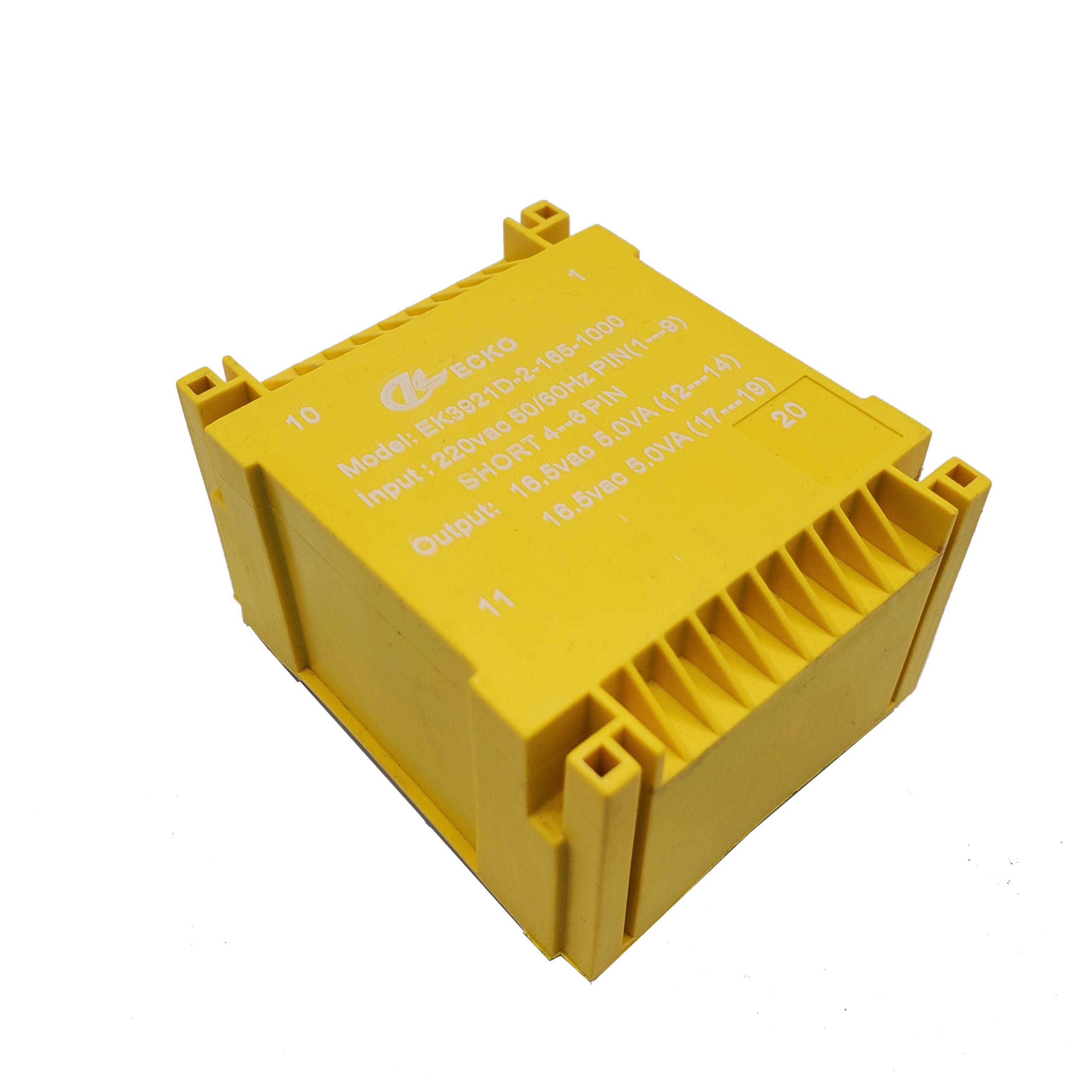
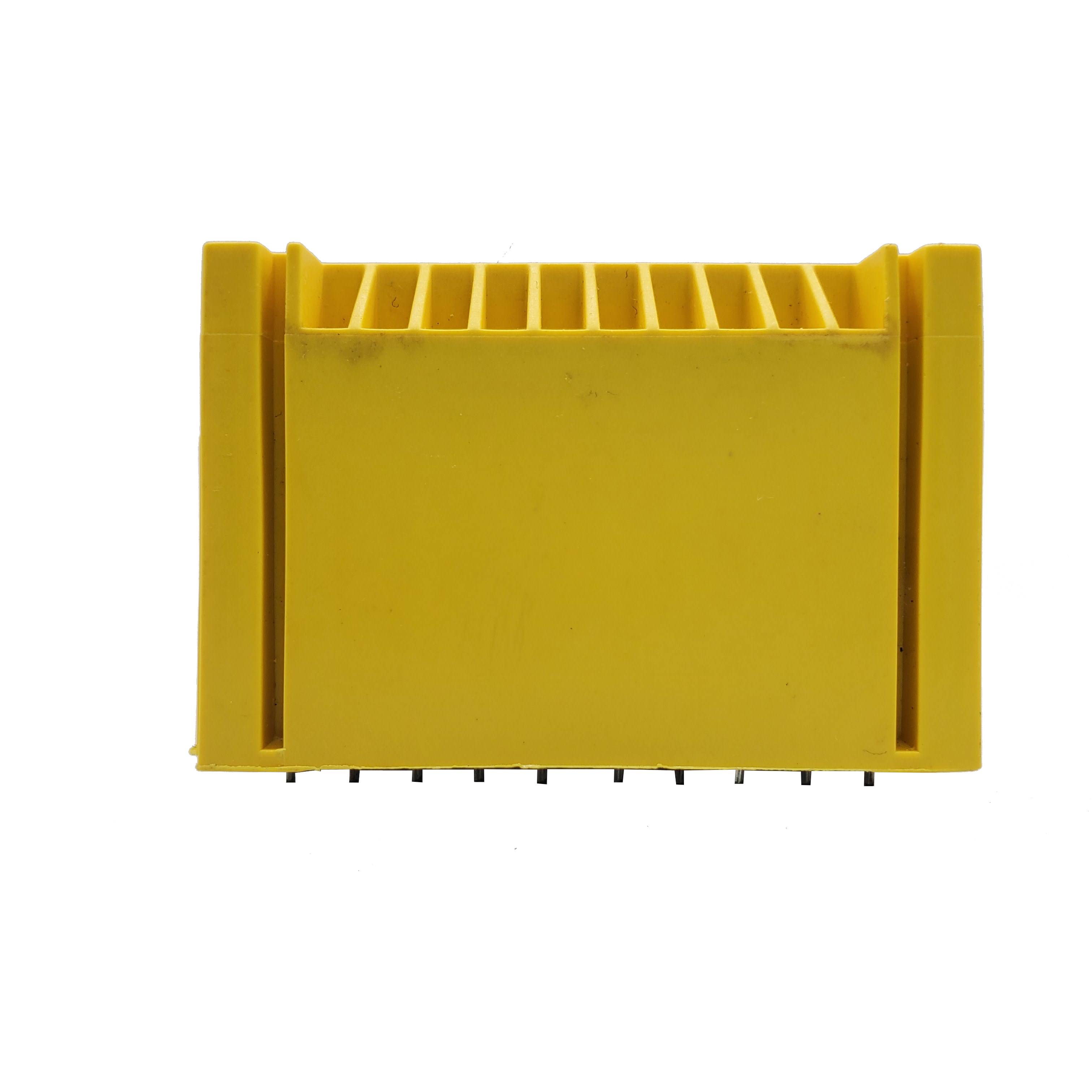
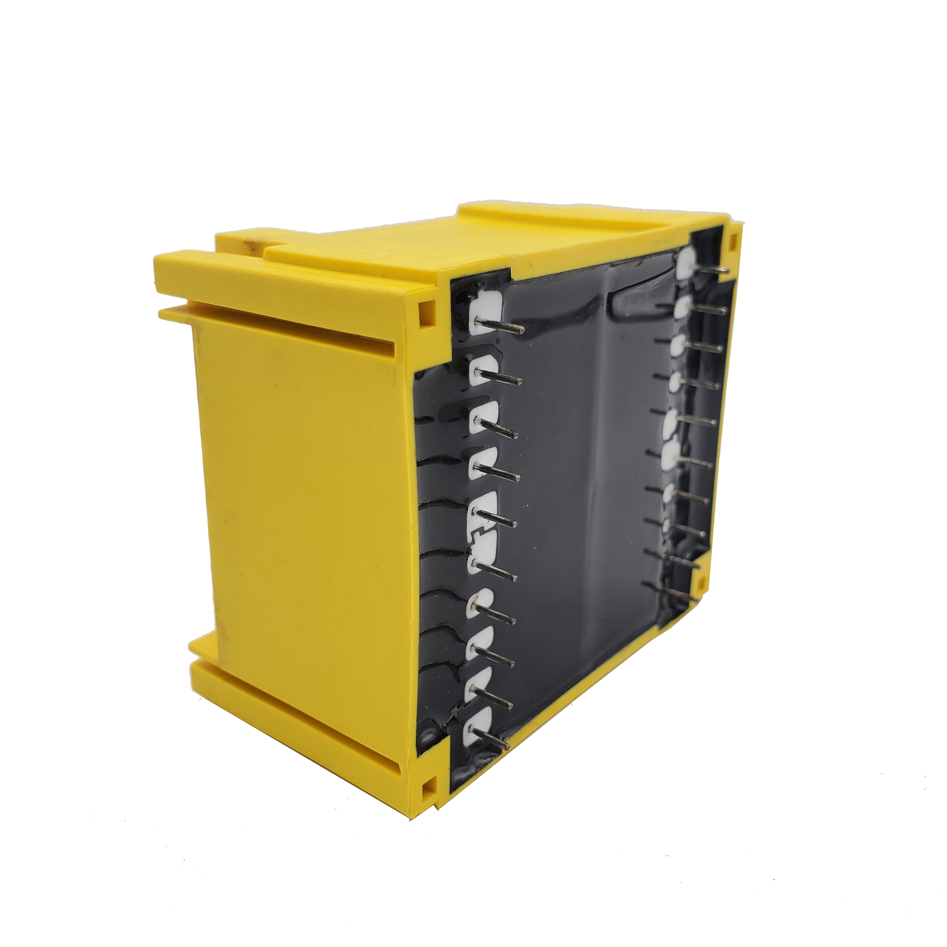
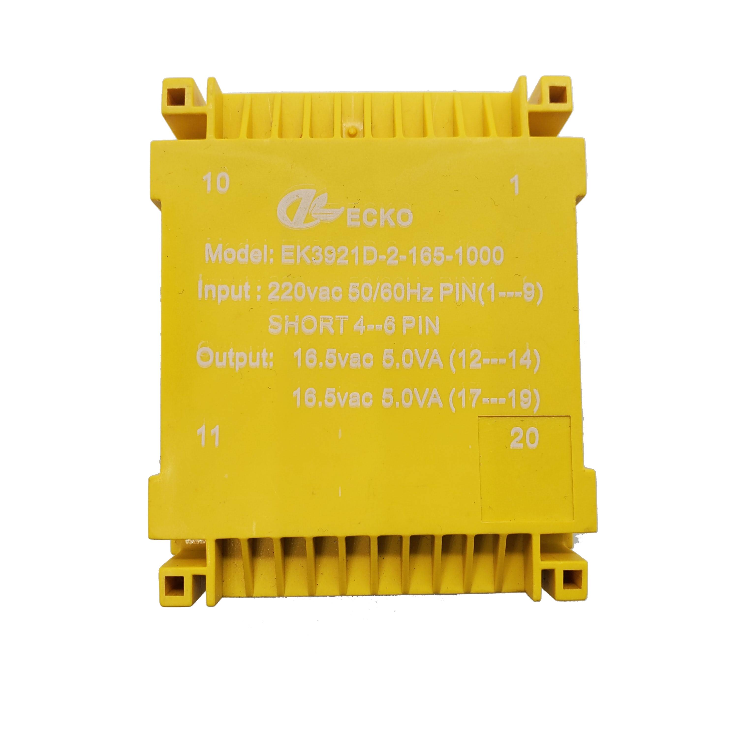
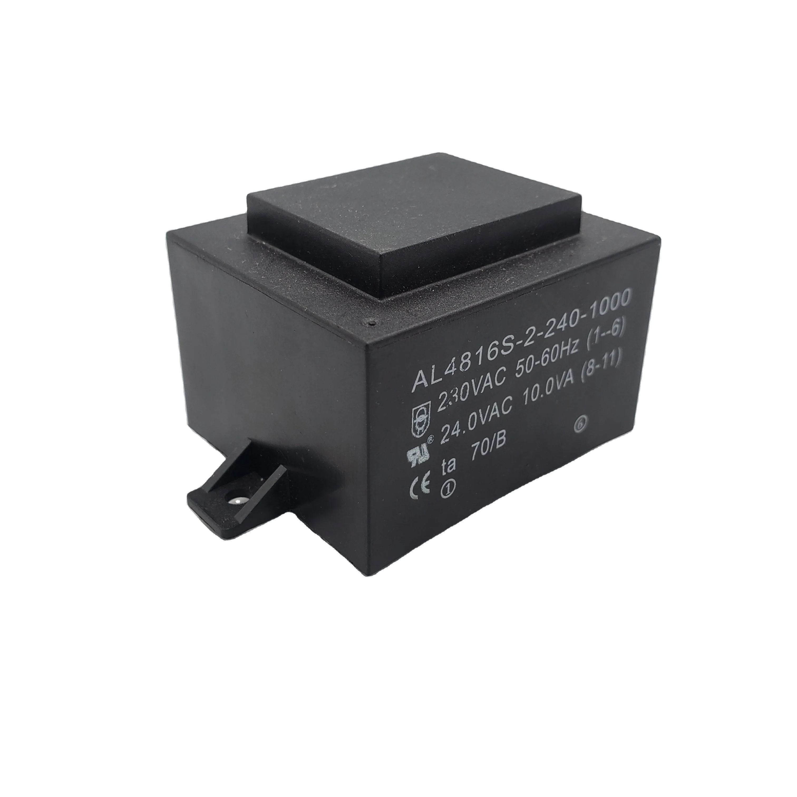
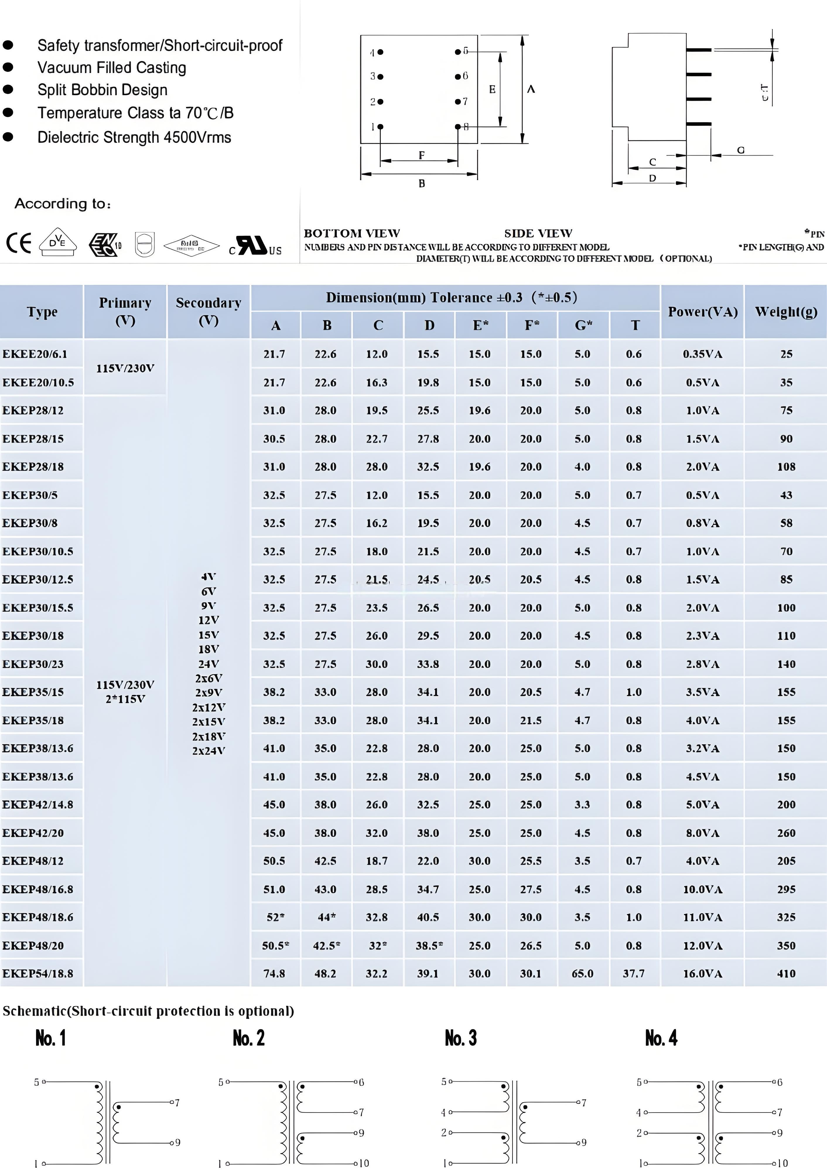
Encapsulated PCB Transformer Specifications
| Parameter |
Typical Range / Available Options |
| Product Type |
Low-frequency encapsulated PCB-mount transformer |
| Construction |
EI laminated core, copper windings, insulated bobbin, protective enclosure and resin encapsulation |
| Rated Power |
Typically 0.5 VA to 60 VA; other ratings subject to engineering review |
| Primary Voltage |
100 V, 110 V, 115 V, 120 V, 127 V, 200 V, 208 V, 220 V, 230 V or 240 V AC |
| Dual Primary Options |
2 × 115 V, 2 × 120 V or other series/parallel configurations |
| Secondary Voltage |
Typically 3 V to 48 V AC; custom voltage available |
| Secondary Configuration |
Single, dual, center-tapped or multiple independent windings |
| Frequency |
50 Hz, 60 Hz or 50/60 Hz |
| Output Type |
Isolated AC output |
| Core Material |
Laminated electrical steel selected according to power, loss and temperature-rise requirements |
| Winding Material |
Specified-grade enameled copper wire |
| Dielectric Strength |
Commonly designed within a 3,000–4,000 VAC range; final voltage and test duration depend on the approved insulation system and applicable standard |
| Insulation Resistance |
Commonly ≥100 MΩ at 500 V DC; final acceptance criteria according to the approved specification |
| Insulation Class |
Class B 130°C or Class F 155°C options |
| Temperature Rise |
Defined according to rated load, ambient temperature, enclosure condition and applicable standard |
| Voltage Regulation |
Optimized according to output voltage, load current, size and temperature-rise requirements |
| Encapsulation |
Flame-retardant epoxy or other resin system selected according to project requirements |
| Housing |
Standard or custom molded enclosure; flame-retardant material options available |
| Mounting |
Through-hole PCB mounting |
| Pin Layout |
Standard or fully customized pin spacing and pin assignment |
| Protection Options |
Thermal fuse, PTC protection, current-limiting design or short-circuit-resistant design where required |
| Shielding Options |
Electrostatic shield between primary and secondary windings |
| Compliance Options |
IEC/EN 61558, UL 5085, CE, UL/cUL, RoHS and REACH requirements, subject to model and project scope |
| Marking |
Model number, electrical rating, date code, batch code, customer logo or private label |
| Packaging |
Individual partitions, trays, cartons and export pallets |
The values above represent common design options rather than the guaranteed specification of every model. Final electrical ratings, dimensions, test limits and compliance requirements are defined in the ECKO-approved product specification and dimensional drawing.
Key Advantages of ECKO Encapsulated PCB Transformers
1. Resin-Encapsulated Protection
The resin encapsulation immobilizes the windings and internal structure, helping protect the transformer against dust, humidity, vibration and handling damage. It also improves mechanical stability during PCB assembly and long-term equipment operation.
Encapsulation alone does not make the transformer waterproof. Outdoor, washdown or high-condensation applications require a separate environmental and IP protection assessment.
|
2. Compact PCB-Mount Design
The enclosed construction combines electrical isolation and voltage conversion in a space-efficient through-hole component. Customized pin layouts help reduce wiring, simplify assembly and fit the available PCB footprint.
|
3. Stable Voltage and Thermal Performance
The core, winding turns, copper wire size and insulation structure are designed around the actual input range, output load and operating environment. This helps achieve controlled voltage regulation, no-load current, losses and temperature rise.
|
4. Application-Specific Electrical Isolation
Basic, supplementary or reinforced insulation can be considered according to the end-product architecture and applicable safety standard. Creepage distance, clearance, insulation tape, bobbin construction and dielectric test requirements are reviewed during development.
|
5. Reduced Mechanical and Acoustic Noise
Resin encapsulation helps limit movement of the core and windings. Combined with controlled core assembly and production processes, it supports stable and low-noise operation in control, instrumentation and indoor electronic equipment.
|
6. Consistent PCB Assembly
Controlled pin positioning, enclosure dimensions and final inspection improve compatibility with automated or manual PCB assembly. Every approved model is manufactured against controlled drawings, material specifications and electrical test limits.
|
Custom Encapsulated PCB Transformer Options
Electrical Customization
- Primary input voltage and input tolerance
- Single or dual primary windings
- Single, dual, center-tapped or multiple secondary outputs
- Rated power and secondary current
- No-load voltage and full-load voltage
- Voltage regulation target
- No-load current and power-loss requirements
- 50 Hz, 60 Hz or universal 50/60 Hz operation
- Basic or reinforced isolation
- Maximum allowable temperature rise
- Continuous, intermittent or application-specific duty cycle
|
Mechanical Customization
- Maximum length, width and height
- PCB pin pitch and row spacing
- Pin diameter, pin length and pin assignment
- Horizontal or vertical PCB-mount construction
- Customer PCB footprint
- Enclosure shape, material and color
- Marking position and orientation
- Customer-specific dimensional tolerances
|
Insulation and Protection Options
- Class B or Class F insulation system
- Thermal fuse embedded in the primary winding
- Resettable PTC protection
- Electrostatic shield with a dedicated grounding pin
- Increased dielectric withstand capability
- Increased creepage and clearance distance
- Short-circuit-resistant design where technically applicable
- Special resin for temperature, humidity or vibration requirements
|
Compliance and Identification
- IEC/EN or UL-oriented construction
- RoHS- and REACH-compliant material options
- UL-recognized insulation materials where required
- Customer logo and private labeling
- Model number, lot number and date-code marking
- Barcode or serialized traceability
- Customer-specific inspection reports and compliance documents
|
Encapsulated PCB Transformer Applications
ECKO encapsulated PCB transformer provide compact AC voltage conversion and electrical isolation for industrial, commercial and consumer electronic assemblies. Each transformer can be customized around the PCB footprint, load profile, operating temperature and safety requirements of the end product.
|
Industrial Control and Automation
Supplies isolated low-voltage AC power for PLC interfaces, relays, contactors, timers, sensors and auxiliary control circuits inside industrial controllers and automation equipment.
|
HVAC and Building Controls
Suitable for thermostats, ventilation controllers, boiler controls, access systems and building automation boards requiring a compact board-mounted transformer.
|
Smart Meters and Energy Management
Provides isolated auxiliary power for metering circuits, monitoring devices, energy controllers and power-management electronics.
|
Security and Access Control Equipment
Can be designed for alarm panels, access controllers, intercom systems and other low-voltage security electronics, subject to the approval requirements of the complete end product.
|
|
Household and Smart-Home Appliances
Supports control boards used in kitchen appliances, environmental controls, smart-home devices and other mains-powered electronic products.
|
Test and Measurement Equipment
Delivers isolated AC power for instrumentation, laboratory controllers and measurement circuits. An electrostatic shield can be added when improved capacitive noise isolation is required.
|
Lighting and LED Control Systems
Suitable for lighting controllers, timers, relay boards and auxiliary power circuits that require reliable isolation from the mains input.
|
Communication and Electronic Control Boards
Provides compact board-level power conversion for communication terminals, interface modules and electronic controllers requiring a line-frequency isolated power source.
|
Why Choose ECKO as Your Encapsulated PCB Transformer Manufacturer?
Engineering Design Based on Your Actual Application
|
ECKO does not select a transformer only by input voltage and VA rating. Our engineering review considers:
- Input voltage range and frequency
- Continuous and peak secondary load
- Required no-load and full-load voltage
- Voltage regulation
- Core flux density
- Copper loss and core loss
- Temperature-rise limit
- Insulation structure
- Creepage and clearance distance
- PCB footprint and enclosure restrictions
- End-product safety and compliance requirements
- The resulting design is balanced for electrical performance, thermal behavior, manufacturability and cost.
|
Revision-Controlled Technical Documents
Every customized model is managed through controlled technical documentation, which may include:
- Customer requirement sheet
- Approved electrical specification
- Dimensional and pin-layout drawing
- Bill of materials
- Winding specification
- Insulation construction
- Process instructions
- Approved test limits
- Sample approval record
- Engineering change record
Drawing, specification and material revisions are identified before production. Changes affecting form, fit, function, safety or approved materials are reviewed through the engineering change process instead of being introduced without control.
|
Controlled Raw Materials
ECKO uses specified-grade enameled copper wire, electrical steel laminations, bobbins, insulation materials, housings, pins and encapsulating resin from controlled sources.
Incoming materials are checked according to the applicable inspection plan. Material grade, dimensions, appearance and compliance documentation can be included in the control process according to project requirements.
|
Integrated Manufacturing Capability
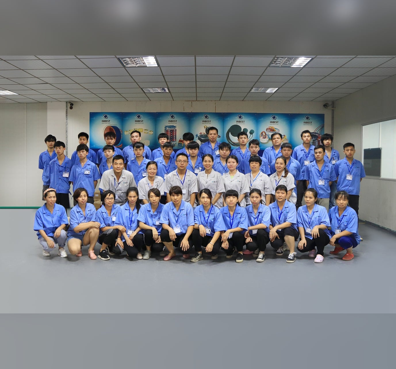
With transformer manufacturing experience since 2000, ECKO operates three workshops covering approximately 5,000 m², supported by around 150 skilled employees and an annual production capacity of up to one million pieces.
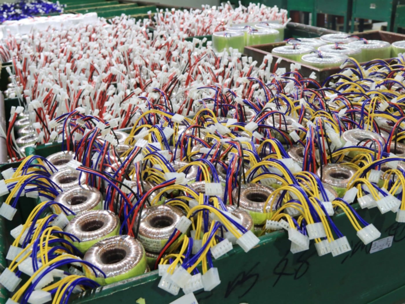
Our production capability covers winding, termination, core assembly, resin dispensing, curing, marking, electrical testing, final inspection and export packaging. This integrated workflow supports prototype development as well as repeat-volume production.
|
Traceable Quality Control
Approved models are manufactured according to controlled drawings, work instructions and test limits. Lot identification, material records and test documentation can be maintained according to the agreed quality plan.
Routine electrical tests are performed before shipment, while temperature rise, overload behavior and environmental tests are completed during qualification or according to customer-specific inspection requirements.
|
|
Testing Items and Acceptance Standards
| Test Item |
Purpose |
Inspection Frequency |
Acceptance Basis |
| Visual Inspection |
Checks housing, resin surface, marking, pins and workmanship |
100% |
Approved appearance criteria and workmanship standard |
| Dimensions and Pin Alignment |
Confirms PCB fit and mechanical tolerances |
According to control plan |
Approved dimensional drawing |
| Winding Continuity |
Detects open circuits and termination faults |
100% |
Electrical specification |
| Winding Resistance |
Confirms winding consistency and connection quality |
According to control plan |
Approved specification and tolerance |
| Turns Ratio and Polarity |
Confirms correct winding ratio and pin assignment |
100% |
Approved electrical diagram |
| No-Load Output Voltage |
Verifies output voltage without load |
100% |
Approved test voltage and tolerance |
| No-Load Input Current |
Evaluates core condition, winding consistency and losses |
According to approved plan |
Approved maximum limit |
| Rated-Load Output Voltage |
Confirms output performance at rated current |
100% or sampling, as agreed |
Approved full-load voltage tolerance |
| Voltage Regulation |
Evaluates the change between no-load and rated-load output |
Design validation or agreed inspection |
Approved specification |
| Dielectric Withstand/Hi-Pot |
Verifies insulation integrity between isolated circuits |
100% |
Approved voltage, duration, leakage-current limit and applicable standard |
| Insulation Resistance |
Checks resistance between isolated windings and accessible conductive parts |
100% or according to control plan |
Approved test voltage and minimum resistance |
| Temperature-Rise Test |
Confirms thermal performance at rated operating conditions |
Sample qualification and periodic verification |
Approved temperature-rise limit and applicable standard |
| Thermal Fuse Function |
Verifies operation of the specified protective device |
Qualification or sampling |
Protective-device specification |
| Overload/Short-Circuit Test |
Evaluates abnormal operating behavior where required |
Design qualification |
Applicable standard and approved safety requirement |
| Terminal Strength |
Checks pin and termination mechanical reliability |
Qualification or periodic sampling |
Approved mechanical test criteria |
| Solderability |
Confirms compatibility with the agreed PCB soldering process |
Qualification or periodic sampling |
Approved solderability criteria |
| Humidity, Thermal Cycling or Vibration |
Evaluates environmental reliability when required |
Customer-specific qualification |
Agreed IEC 60068 method or customer standard |
| RoHS Substance Verification |
Supports restricted-substance compliance |
Material documentation or laboratory testing |
Applicable regulatory limit and IEC 62321 test method |
Custom Encapsulated PCB Transformer Development Process
Step 1: Submit Your Requirements
Provide the input voltage, frequency, output voltage and current, power rating, PCB footprint, maximum dimensions, operating environment and target compliance requirements.
|
Step 2: Engineering Feasibility Review
ECKO evaluates the electrical loading, core size, winding arrangement, insulation structure, temperature rise, pin layout and manufacturability.
|
Step 3: Design Proposal and Quotation
We provide the proposed electrical configuration, mechanical solution, commercial quotation, tooling requirement if applicable and estimated development schedule.
|
Step 4: Specification and Drawing Approval
The electrical specification, outline dimensions, pin assignment, tolerances, test limits, marking and protection features are confirmed before sample production.
|
Step 5: Prototype Manufacturing
Samples are manufactured according to the approved development documents. Critical electrical and mechanical characteristics are inspected before shipment.
|
Step 6: Sample Testing and Customer Approval
The customer evaluates the samples in the actual PCB and end equipment. Any required design adjustments are reviewed, documented and verified.
|
Step 7: Pilot Production
A pilot run can be arranged to verify production repeatability, assembly compatibility, material control and test consistency before volume production.
|
Step 8: Mass Production and Shipment
Mass production is completed according to the approved specification, BOM, process instructions and inspection plan. Final products are tested, packed and shipped with the agreed documents.
|
|
Encapsulated PCB Transformer FAQ
1. Can you customize an encapsulated PCB transformer according to our PCB layout?
Yes. Customers can provide PCB drawings, Gerber information, pin coordinates, or mechanical drawings, and we can evaluate a transformer design that fits the available PCB space.
2. Can the PCB pin spacing be customized?
Yes. Pin spacing, pin diameter, pin quantity, pin position, and pin configuration can be customized according to PCB requirements.
3. Can you customize the transformer height?
Yes. We can evaluate different core sizes, bobbins, and winding structures to achieve the required height while maintaining electrical and thermal performance.
4. Can you customize the housing shape?
Yes. Housing structures can be customized for suitable projects, especially when there are specific PCB space or mechanical installation requirements.
5. Can you customize lead wires instead of PCB pins?
Yes. Depending on the design, transformers can be supplied with PCB pins, lead wires, terminals, connectors, or a combination of connection methods.
6. Can wire colors and lengths be customized?
Yes. Lead wire length, color, insulation type, stripping length, and terminal type can be customized according to customer drawings.
7. Can you add an electrostatic shield?
Yes. An electrostatic shield between primary and secondary windings can be added where improved noise suppression or reduced capacitive coupling is required.
8. Can you customize the transformer for low-profile equipment?
Yes. Low-profile designs can be evaluated according to the available PCB area, height limitation, required power, and temperature-rise requirement.
9. Can you design a replacement for a discontinued transformer?
Yes. If the original specification, sample, dimensions, electrical parameters, or PCB footprint are available, we can evaluate a compatible replacement solution.
10. Do you support completely new transformer designs?
Yes. Our engineering team can develop custom encapsulated PCB transformers from initial electrical specifications through prototyping, validation, and mass production.
 EN
EN