EN
EN


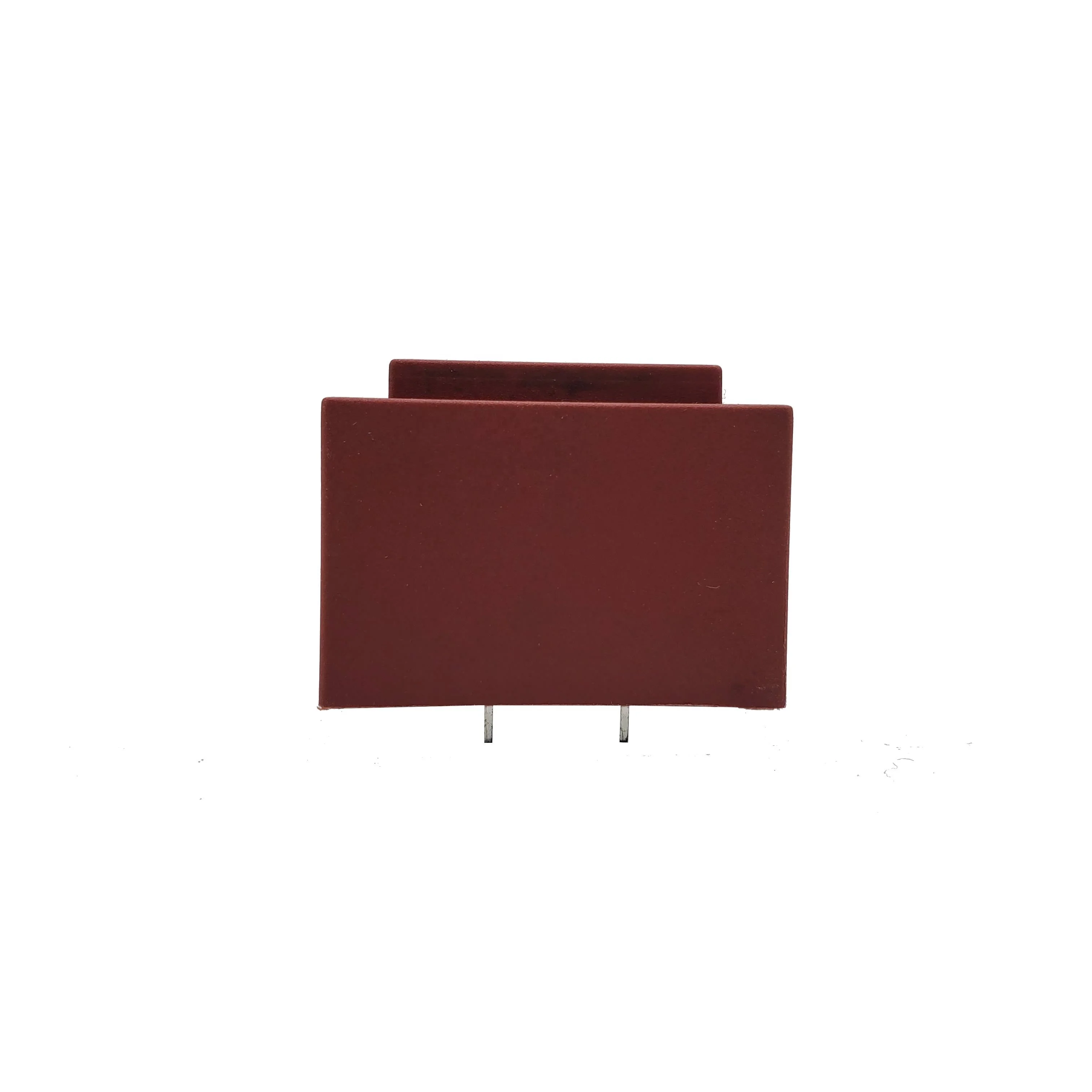
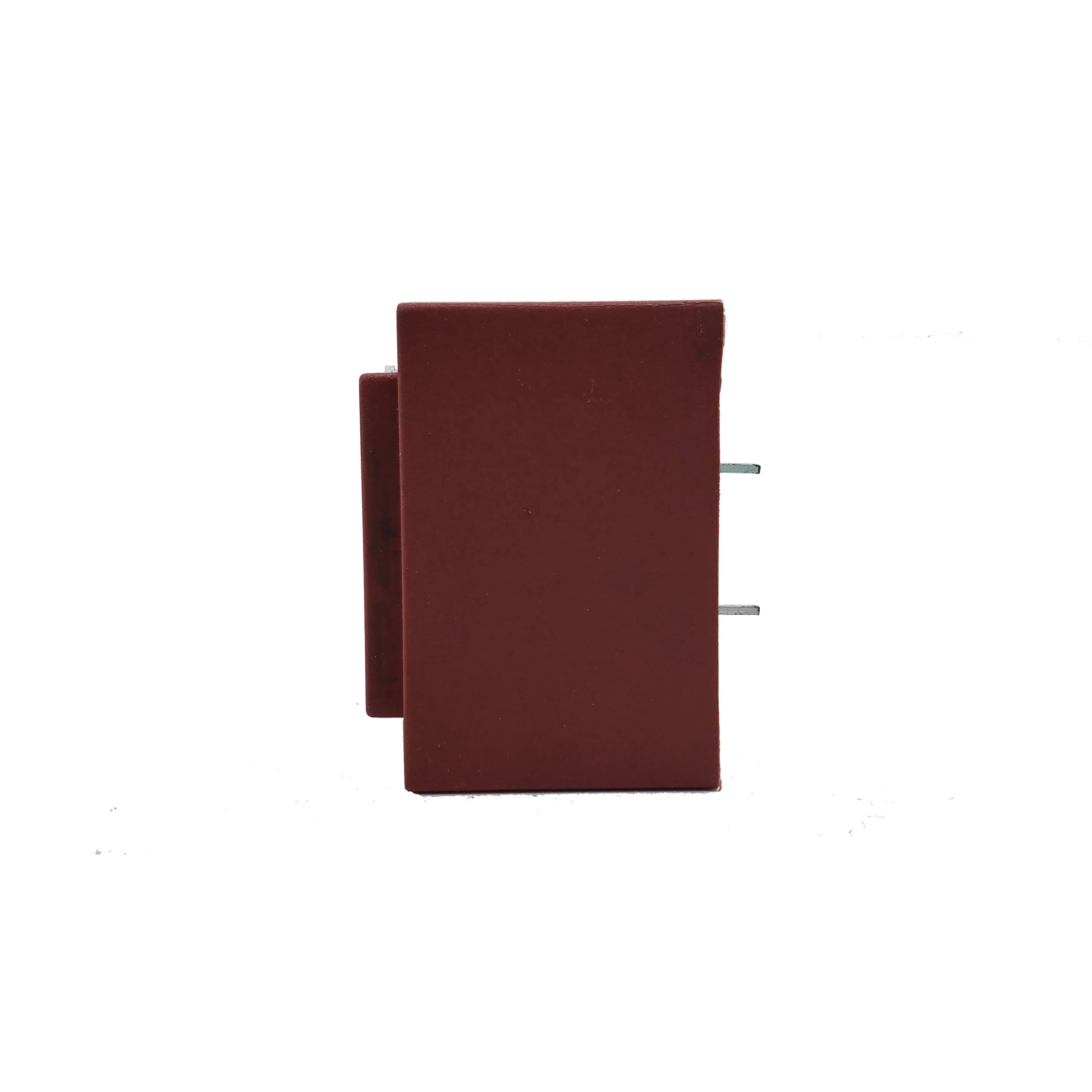
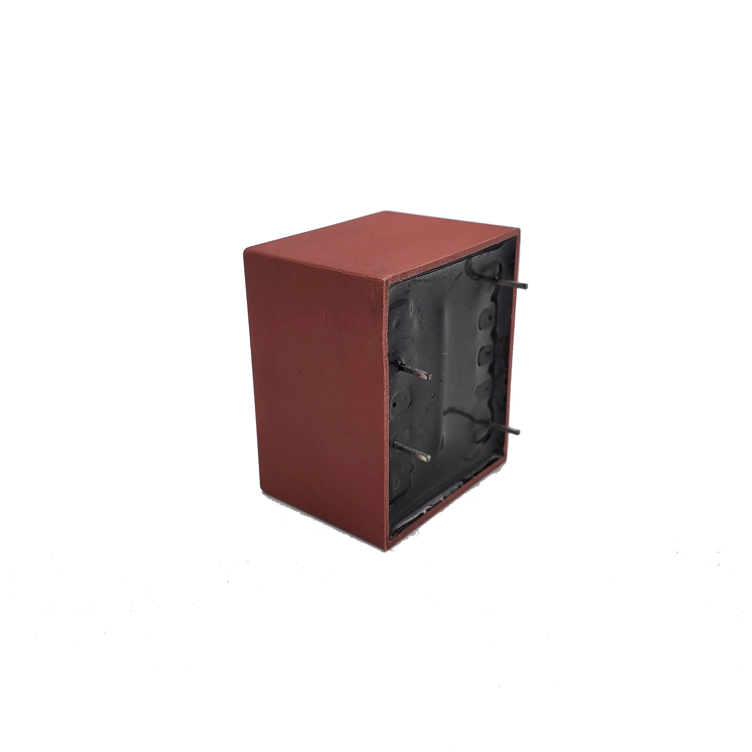
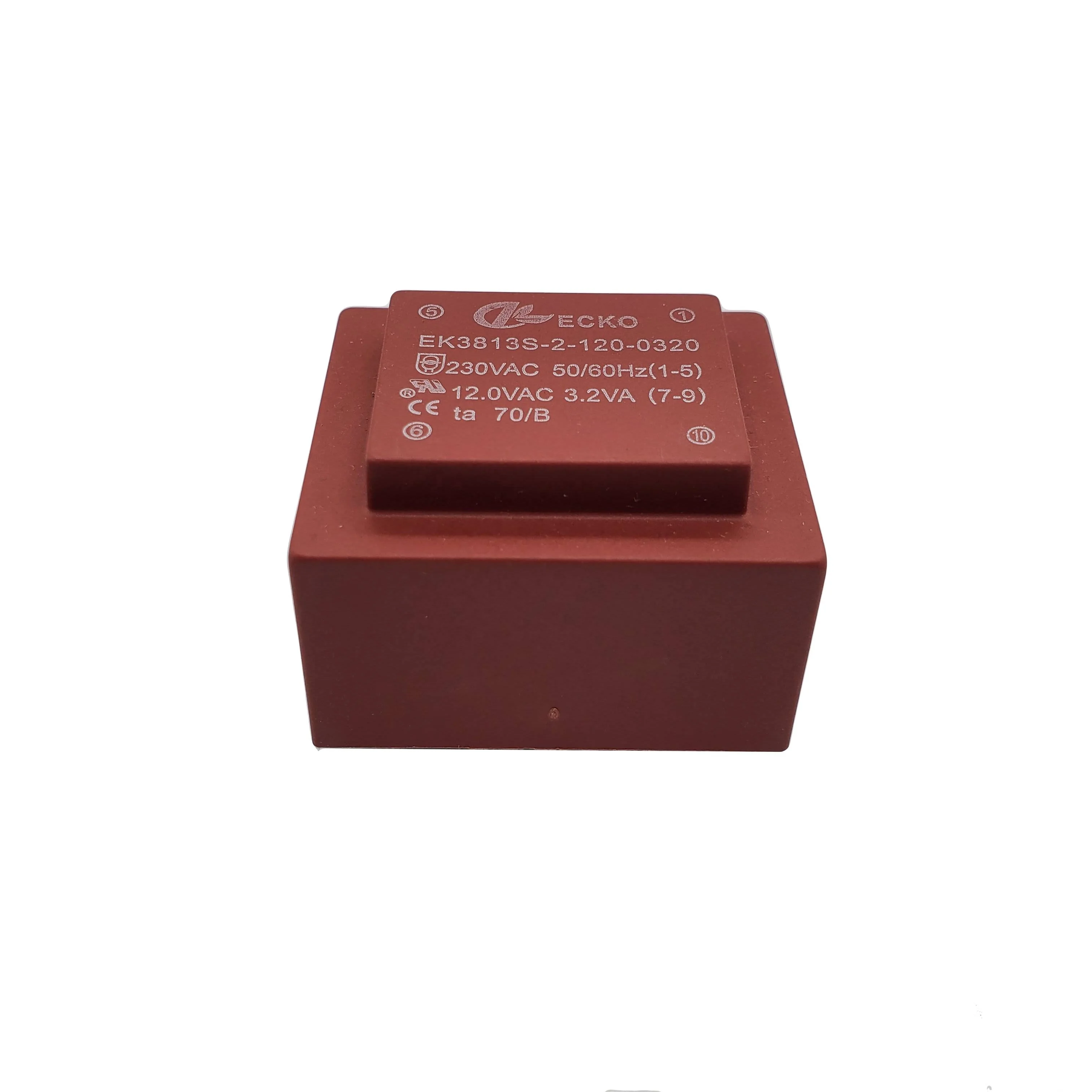
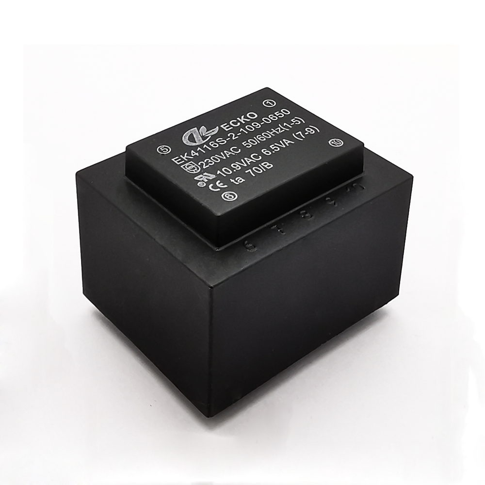
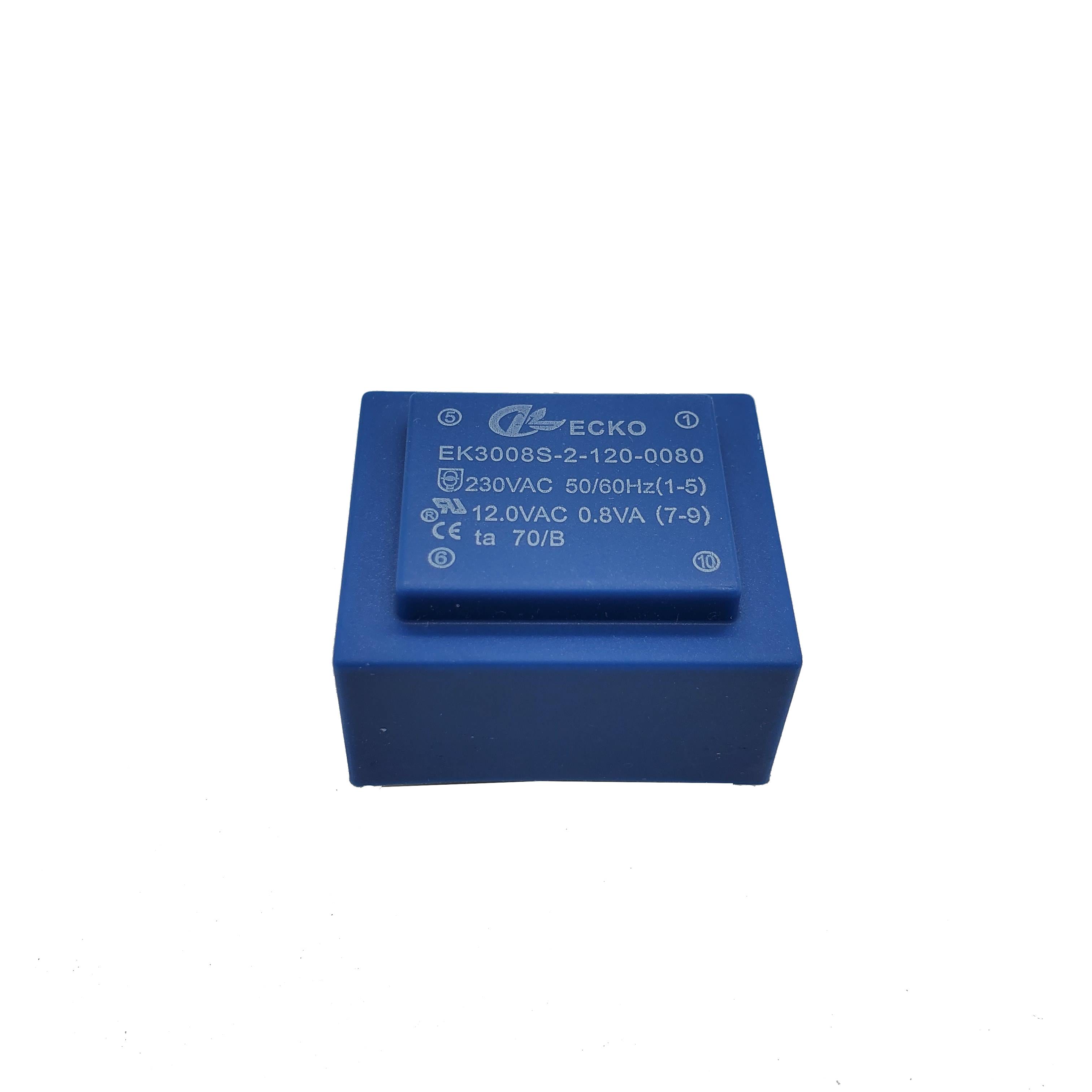
Dual Output Encapsulated PCB Transformer for PCB Power Supply Systems
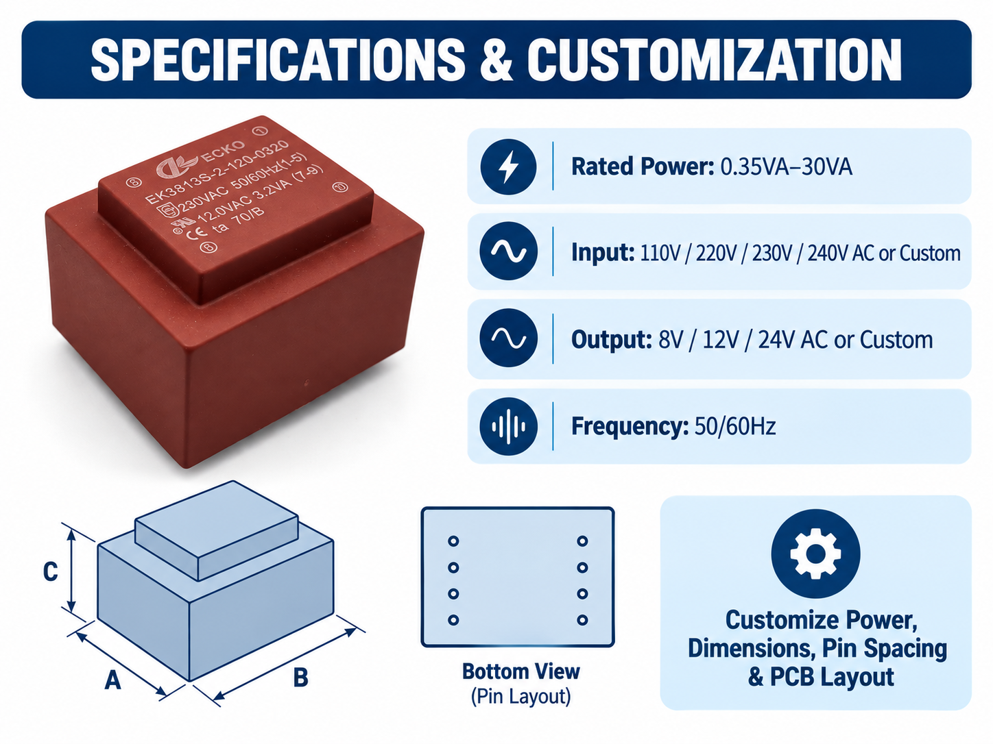
Custom transformer with single, dual or multiple secondary windings, supporting tailored AC output voltages for control boards, relays, sensors and electronic modules.
| Parameter | Typical Range / Available Options |
|---|---|
| Product Type | Low-frequency encapsulated PCB-mount transformer |
| Construction | EI laminated core, copper windings, insulated bobbin, protective enclosure and resin encapsulation |
| Rated Power | Typically 0.5 VA to 60 VA; other ratings subject to engineering review |
| Primary Voltage | 100 V, 110 V, 115 V, 120 V, 127 V, 200 V, 208 V, 220 V, 230 V or 240 V AC |
| Dual Primary Options | 2 × 115 V, 2 × 120 V or other series/parallel configurations |
| Secondary Voltage | Typically 3 V to 48 V AC; custom voltage available |
| Secondary Configuration | Single, dual, center-tapped or multiple independent windings |
- Overview
- Recommended Products
Encapsulated PCB Transformer Specifications
The values above represent common design options rather than the guaranteed specification of every model. Final electrical ratings, dimensions, test limits and compliance requirements are defined in the ECKO-approved product specification and dimensional drawing.
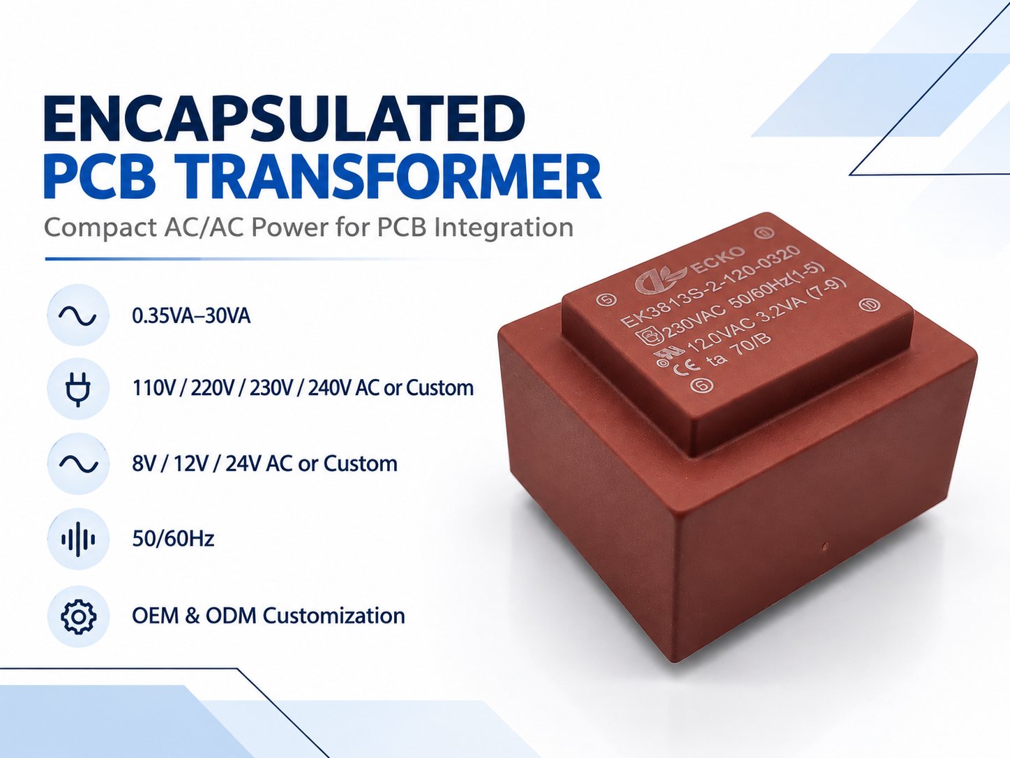
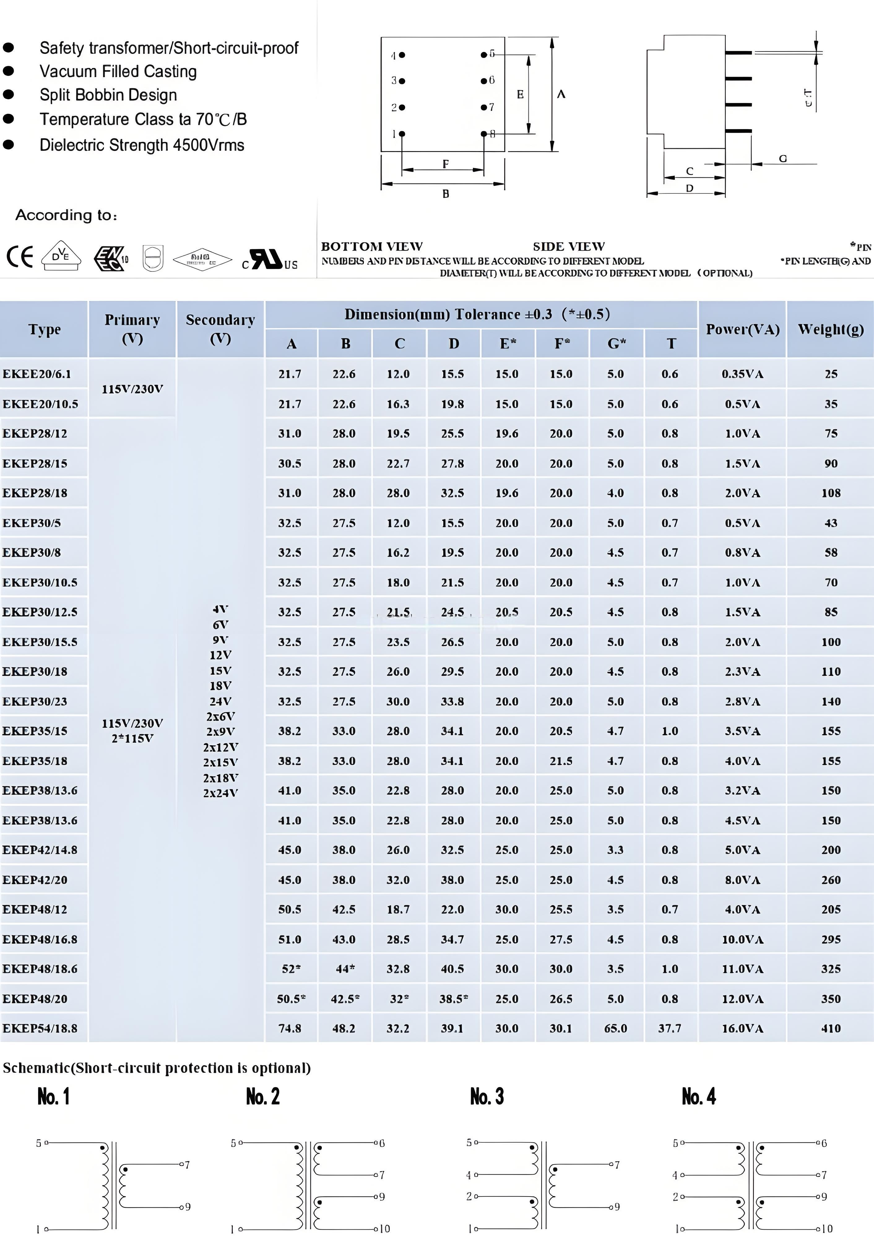
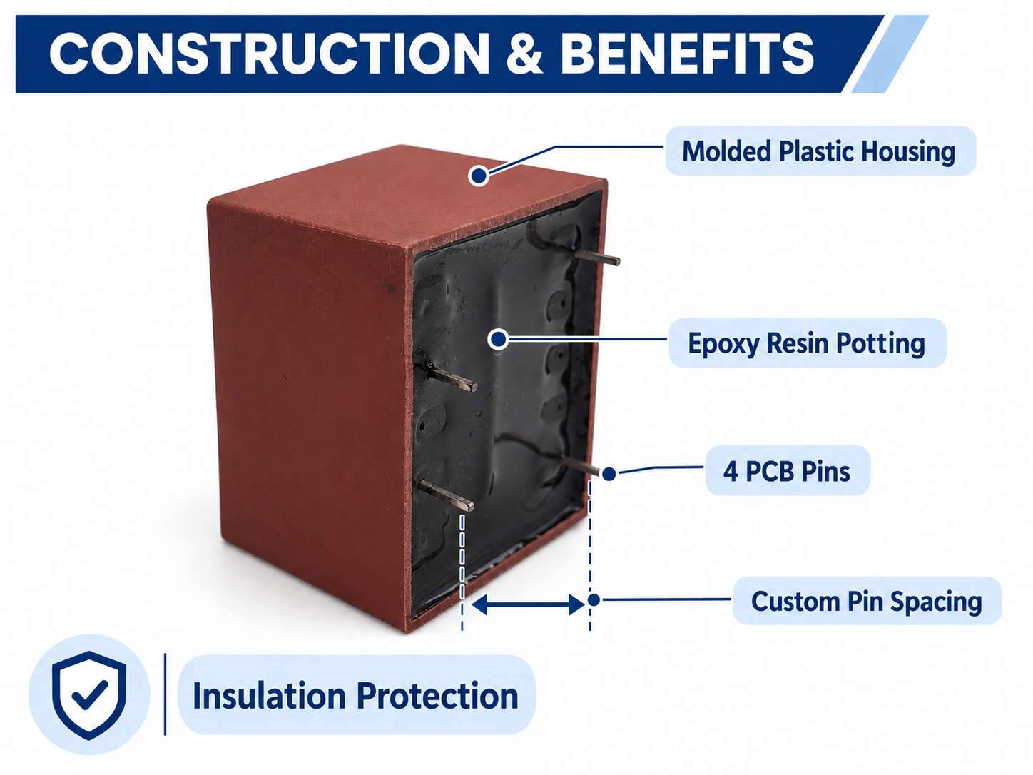
Key Advantages of ECKO Encapsulated PCB Transformers
Custom Encapsulated PCB Transformer Options
Encapsulated PCB Transformer Applications
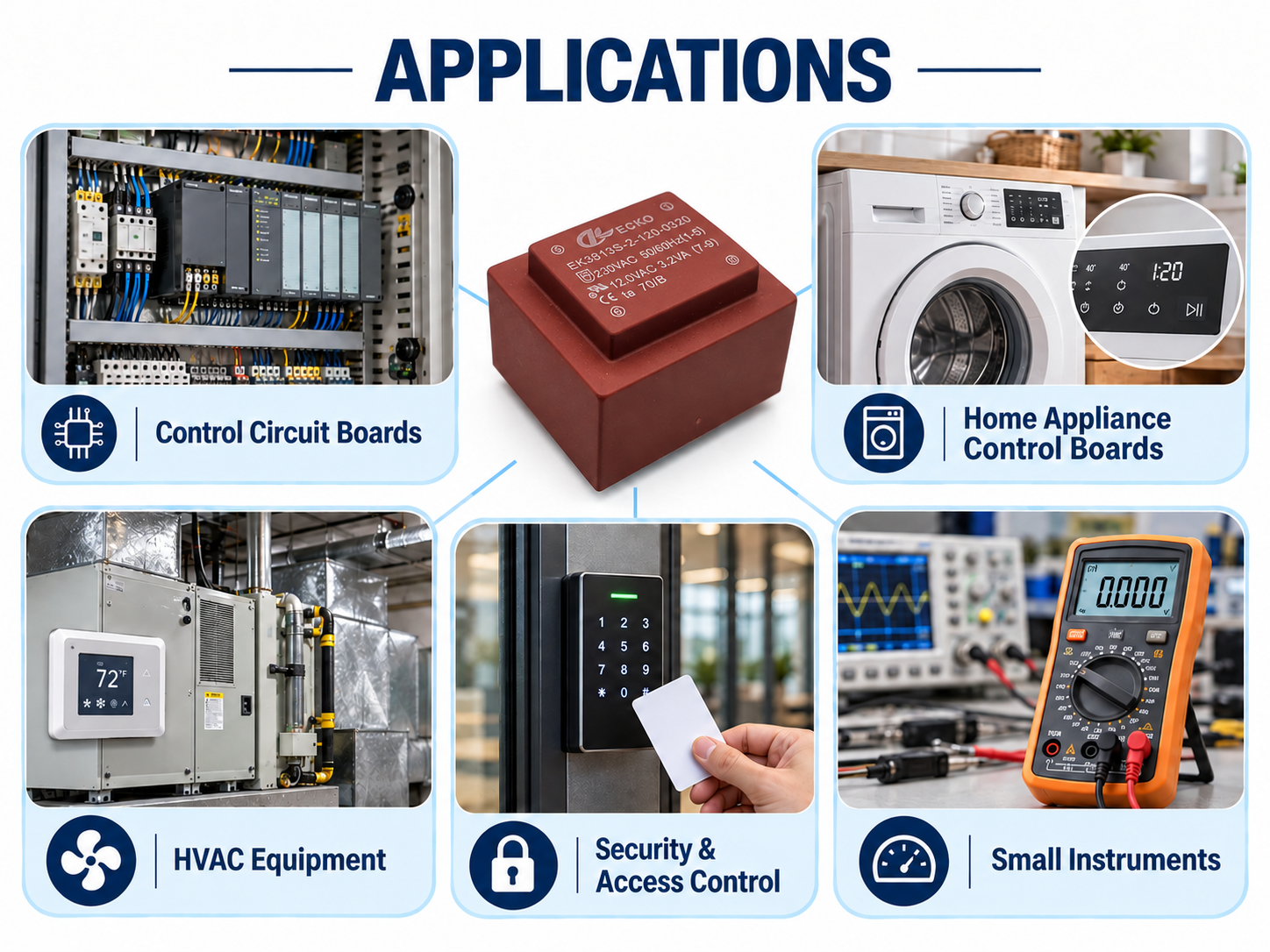
ECKO encapsulated PCB transformer provide compact AC voltage conversion and electrical isolation for industrial, commercial and consumer electronic assemblies. Each transformer can be customized around the PCB footprint, load profile, operating temperature and safety requirements of the end product.
Why Choose ECKO as Your Encapsulated PCB Transformer Manufacturer?
Engineering Design Based on Your Actual Application
Testing Items and Acceptance Standards
| Test Item | Purpose | Inspection Frequency | Acceptance Basis |
| Visual Inspection | Checks housing, resin surface, marking, pins and workmanship | 100% | Approved appearance criteria and workmanship standard |
| Dimensions and Pin Alignment | Confirms PCB fit and mechanical tolerances | According to control plan | Approved dimensional drawing |
| Winding Continuity | Detects open circuits and termination faults | 100% | Electrical specification |
| Winding Resistance | Confirms winding consistency and connection quality | According to control plan | Approved specification and tolerance |
| Turns Ratio and Polarity | Confirms correct winding ratio and pin assignment | 100% | Approved electrical diagram |
| No-Load Output Voltage | Verifies output voltage without load | 100% | Approved test voltage and tolerance |
| No-Load Input Current | Evaluates core condition, winding consistency and losses | According to approved plan | Approved maximum limit |
| Rated-Load Output Voltage | Confirms output performance at rated current | 100% or sampling, as agreed | Approved full-load voltage tolerance |
| Voltage Regulation | Evaluates the change between no-load and rated-load output | Design validation or agreed inspection | Approved specification |
| Dielectric Withstand/Hi-Pot | Verifies insulation integrity between isolated circuits | 100% | Approved voltage, duration, leakage-current limit and applicable standard |
| Insulation Resistance | Checks resistance between isolated windings and accessible conductive parts | 100% or according to control plan | Approved test voltage and minimum resistance |
| Temperature-Rise Test | Confirms thermal performance at rated operating conditions | Sample qualification and periodic verification | Approved temperature-rise limit and applicable standard |
| Thermal Fuse Function | Verifies operation of the specified protective device | Qualification or sampling | Protective-device specification |
| Overload/Short-Circuit Test | Evaluates abnormal operating behavior where required | Design qualification | Applicable standard and approved safety requirement |
| Terminal Strength | Checks pin and termination mechanical reliability | Qualification or periodic sampling | Approved mechanical test criteria |
| Solderability | Confirms compatibility with the agreed PCB soldering process | Qualification or periodic sampling | Approved solderability criteria |
| Humidity, Thermal Cycling or Vibration | Evaluates environmental reliability when required | Customer-specific qualification | Agreed IEC 60068 method or customer standard |
| RoHS Substance Verification | Supports restricted-substance compliance | Material documentation or laboratory testing | Applicable regulatory limit and IEC 62321 test method |
Custom Encapsulated PCB Transformer Development Process
Encapsulated PCB Transformer FAQ
1. What information should we provide about our PCB?
Please provide available PCB area, transformer footprint, pin coordinates, maximum height, input/output requirements, mounting restrictions, and any required safety distances.
2. Can you provide a PCB footprint drawing?
Yes. A mechanical drawing showing transformer dimensions, pin positions, pin spacing, and recommended PCB footprint can be supplied for approved designs.
3. Can the pin arrangement match our existing PCB?
Yes. Existing PCB pin arrangements can often be matched when the electrical design and mechanical structure allow it.
4. What mounting method is used for encapsulated PCB transformers?
Most encapsulated PCB transformers use through-hole PCB pins and are soldered directly to the printed circuit board.
5. How should the transformer be positioned on the PCB?
The transformer should be positioned with consideration for electrical safety distances, heat-sensitive components, high-voltage circuits, airflow, and mechanical clearance.
6. Should additional mechanical fixing be used?
Small transformers may be supported sufficiently by PCB pins, while larger or heavier transformers may require additional mechanical support depending on vibration and transportation conditions.
7. Can you provide pin numbering on the transformer?
Yes. Pin numbering can be marked on the drawing, housing, or product label depending on the design.
8. Can primary and secondary pins be separated on opposite sides?
Yes. This is a common structure and can help maintain electrical separation between primary and secondary circuits.
9. Can you manufacture a transformer for automated PCB assembly?
Yes. Product dimensions, pin straightness, pin length, packaging, and other requirements can be evaluated according to the customer's assembly process.
10. Can you provide 2D or 3D drawings for PCB design?
2D dimensional drawings are commonly available. Additional engineering files can be discussed depending on the project requirements.