EN
EN

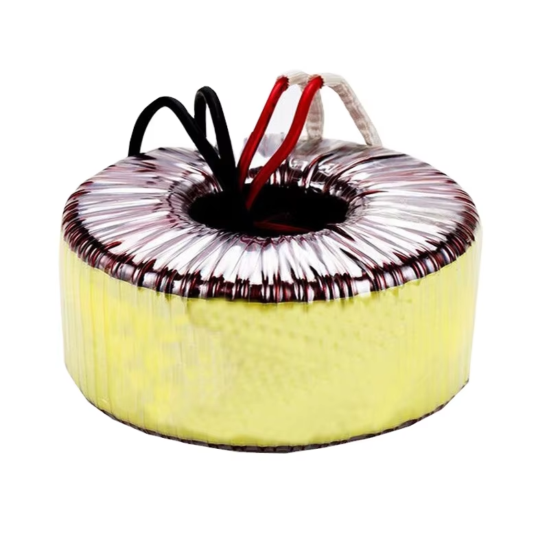
Ensuring proper cooling and installation for toroidal transformers is critical to achieving optimal performance, extending operational lifespan, and preventing premature failure in demanding electrical applications. Toroidal transformers are widely recognized for their compact design, high efficiency, and superior electromagnetic characteristics, yet these advantages can only be fully realized when thermal management and installation practices adhere to engineering best practices. Inadequate cooling compromises winding integrity, accelerates insulation degradation, and reduces power handling capacity, while improper installation introduces mechanical stress, electrical hazards, and noise issues that undermine system reliability. This comprehensive guide examines the technical principles, practical methodologies, and field-tested strategies necessary to maintain safe operating temperatures and execute mechanically sound installations across industrial, audio, medical, and power supply environments.
The unique doughnut-shaped geometry of toroidal transformers offers significant thermal and electrical advantages over conventional laminated designs, including reduced core losses and concentrated magnetic fields that minimize stray flux. However, this compact construction also concentrates heat generation within a smaller volume, making effective heat dissipation mechanisms essential to prevent localized hotspots that can damage windings and core materials. Understanding the interplay between ambient conditions, load profiles, mounting configurations, and airflow patterns enables engineers and technicians to implement cooling solutions that align with manufacturer specifications while accommodating real-world operational constraints. Similarly, installation procedures must address mounting orientation, vibration isolation, electrical clearances, and grounding requirements to ensure both electrical safety and long-term mechanical stability in diverse application contexts.
Understanding Thermal Challenges in Toroidal Transformer Operation
Heat Generation Mechanisms and Thermal Distribution Patterns
Heat generation in toroidal transformers originates from two primary sources: core losses resulting from hysteresis and eddy currents within the laminated steel core, and copper losses caused by resistive heating in the primary and secondary windings. The toroidal geometry concentrates these heat sources within a relatively compact form factor, creating thermal gradients that vary significantly between the inner diameter, outer surface, and winding layers. Core losses remain relatively constant regardless of load conditions, while copper losses increase proportionally with the square of the load current, making high-duty-cycle applications particularly susceptible to thermal stress. The inner portions of toroidal transformers typically experience higher temperatures due to restricted airflow access and longer thermal paths to dissipation surfaces, necessitating careful attention to winding distribution and insulation material selection during the manufacturing process.
Thermal distribution within toroidal transformers follows predictable patterns influenced by core material properties, winding configuration, and external cooling conditions. The outer surface of the toroid typically operates at lower temperatures than internal regions due to direct exposure to ambient air, while the center hole provides a secondary heat dissipation pathway when properly utilized. Temperature differentials between winding layers can reach significant levels under sustained high-load conditions, particularly in designs with multiple secondary windings or high current-carrying capacity. These thermal gradients create expansion and contraction cycles that stress insulation systems and solder joints, emphasizing the importance of thermal management strategies that maintain uniform temperature distribution across all transformer components. Engineers must account for these heat distribution patterns when specifying cooling requirements and selecting installation locations to prevent localized overheating that can compromise transformer integrity.
Temperature Rating Standards and Safe Operating Limits
Industry standards establish specific temperature rise limits for toroidal transformers based on insulation class ratings and expected operational environments. Class A insulation systems, commonly used in consumer electronics and light industrial applications, permit maximum winding temperatures of 105 degrees Celsius with typical temperature rises of 55-60 degrees above ambient under full load conditions. Class B and Class F systems, employed in more demanding applications, allow higher operating temperatures of 130 and 155 degrees Celsius respectively, providing greater thermal margins for continuous high-load operation. These ratings incorporate safety factors that account for localized hotspots, measurement uncertainties, and aging effects, but they assume proper cooling provisions and installation practices that facilitate heat transfer to the surrounding environment.
Safe operating limits for toroidal transformers must consider both steady-state thermal conditions and transient overload scenarios that temporarily elevate temperatures beyond nominal ratings. Continuous operation at or near maximum rated temperature accelerates insulation aging through thermal, electrical, and mechanical stress mechanisms, effectively reducing expected service life according to well-established degradation models. The relationship between operating temperature and insulation life expectancy follows an exponential curve, where each 10-degree Celsius increase in average winding temperature can halve the expected operational lifespan. Consequently, implementing cooling strategies that maintain operating temperatures well below maximum ratings provides substantial reliability benefits, particularly in mission-critical applications where unplanned downtime carries significant operational or financial consequences. Temperature monitoring provisions, whether through embedded thermistors or infrared surface measurements, enable proactive thermal management and early detection of cooling system deficiencies before they progress to transformer failure.
Implementing Effective Cooling Strategies for Toroidal Transformers
Natural Convection Cooling Design Principles
Natural convection represents the most common and cost-effective cooling method for toroidal transformers operating at moderate power levels in applications where ambient temperatures remain within acceptable ranges. This passive cooling approach relies on buoyancy-driven airflow patterns created as heated air surrounding the transformer rises and draws cooler ambient air into contact with heat-dissipating surfaces. The effectiveness of natural convection cooling depends critically on maintaining unobstructed air circulation paths around all transformer surfaces, particularly the outer diameter and center hole regions where thermal transfer occurs most efficiently. Minimum clearance requirements typically specify 25-50 millimeters of open space on all sides of toroidal transformers to ensure adequate airflow development, with larger clearances recommended for higher power ratings or elevated ambient temperatures.
Mounting orientation significantly influences natural convection cooling performance for toroidal transformers, with vertical mounting positions generally providing superior thermal performance compared to horizontal orientations. When mounted with the toroid axis vertical, heated air can rise freely through the center hole, creating a chimney effect that enhances airflow velocity and heat transfer coefficients across internal surfaces. Horizontal mounting reduces this beneficial effect and may create stagnant air pockets within the center hole region, particularly in enclosed installations where surrounding equipment restricts lateral airflow. Engineers should prioritize vertical mounting whenever mechanical constraints permit, and must increase derating factors or implement supplementary cooling measures when horizontal orientations prove necessary. Additionally, avoiding installation locations directly above other heat-generating components prevents pre-heated air from entering the transformer cooling zone, which would reduce the effective temperature differential driving convection currents and diminish overall cooling capacity.
Forced Air Cooling Implementation Methods
Forced air cooling becomes necessary when toroidal transformers operate at higher power levels, in elevated ambient temperatures, or in enclosed spaces where natural convection proves insufficient to maintain acceptable operating temperatures. This active cooling approach employs fans or blowers to establish controlled airflow patterns across transformer surfaces, significantly enhancing heat transfer coefficients and thermal dissipation capacity compared to passive methods. Effective forced air cooling system design requires careful consideration of airflow direction, velocity, coverage uniformity, and noise generation to achieve thermal objectives without introducing unacceptable acoustic emissions or air turbulence that might affect adjacent sensitive equipment. Airflow should ideally target both the outer surface and center hole of toroidal transformers, with flow rates calculated based on thermal dissipation requirements and available pressure differential across the cooling path.
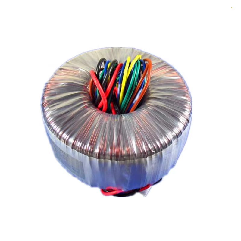
Fan selection for forced air cooling of toroidal transformers must balance thermal performance requirements against acoustic considerations, power consumption constraints, and reliability expectations. Axial fans positioned to direct airflow through the transformer center hole provide efficient cooling for the critical inner winding regions while maintaining relatively compact installation footprints. Alternatively, tangential or centrifugal blowers can deliver higher static pressure capabilities suitable for ducted cooling systems or installations requiring airflow through restrictive paths. Fan sizing calculations should target air velocities between 1.5 and 3 meters per second across transformer surfaces to achieve meaningful thermal performance improvements without generating excessive acoustic noise or aerodynamic turbulence. Redundant fan configurations merit consideration in critical applications where cooling system failure could compromise transformer operation, with automatic switchover controls activating backup cooling capacity upon primary fan failure detection. Regular maintenance intervals should include fan bearing inspection, blade cleaning, and airflow verification to ensure sustained cooling effectiveness throughout the transformer service life.
Heat Sink and Thermal Interface Material Applications
Supplementary heat dissipation components extend the thermal management capabilities of toroidal transformers beyond airflow-dependent cooling methods alone. Custom-designed aluminum heat sinks attached to transformer mounting surfaces provide increased surface area for heat rejection, particularly beneficial in space-constrained installations where airflow development remains limited. These heat sink assemblies typically incorporate fins or extended surfaces oriented to promote natural or forced convection airflow patterns, with thermal interface materials ensuring efficient heat transfer from the transformer mounting surface into the heat sink structure. The effectiveness of heat sink applications depends on maintaining intimate physical contact across the entire mounting interface, requiring flat, smooth mating surfaces and appropriate fastener torque specifications to minimize thermal resistance at the critical junction between transformer and heat dissipation component.
Thermal interface materials play essential roles in optimizing heat transfer between toroidal transformers and heat dissipation structures or mounting surfaces. These specialized compounds fill microscopic air gaps and surface irregularities that would otherwise create insulating barriers impeding thermal conduction from the transformer case to heat sinks or chassis mounting points. Common thermal interface materials include silicone-based thermal compounds, phase-change materials that liquify at operating temperatures, and thermally conductive adhesive pads that provide both heat transfer and mechanical bonding functions. Selection criteria must balance thermal conductivity specifications, electrical insulation requirements, operating temperature ranges, and long-term stability characteristics to ensure sustained performance throughout anticipated service conditions. Application procedures should follow manufacturer guidelines regarding layer thickness, surface preparation, and curing requirements to achieve specified thermal resistance values and avoid performance degradation from excessive compound thickness or incomplete surface coverage.
Executing Proper Installation Procedures for Toroidal Transformers
Mechanical Mounting Configuration and Hardware Selection
Proper mechanical mounting of toroidal transformers requires specialized hardware and techniques that accommodate their unique geometry while providing secure attachment, vibration isolation, and electrical safety. The standard mounting method employs a center bolt that passes through the transformer center hole, with insulating washers separating the mounting hardware from the core and windings to prevent electrical contact and potential ground loops. Mounting bolt selection must consider both mechanical strength requirements and electromagnetic compatibility, with non-magnetic stainless steel hardware preferred to avoid introducing magnetic circuit disturbances that could affect transformer performance. Fastener torque specifications provided by transformer manufacturers balance the competing requirements of secure mechanical attachment against excessive compression forces that might stress core laminations or winding structures, typically ranging between 3 and 8 Newton-meters depending on transformer size and mounting configuration.
Vibration isolation represents a critical consideration for toroidal transformer installations in applications experiencing mechanical shock, continuous vibration exposure, or stringent acoustic noise requirements. Elastomeric mounting grommets or isolation washers positioned between the transformer and mounting surface absorb vibration energy while maintaining adequate electrical insulation and heat transfer characteristics. These isolation components must provide sufficient compliance to attenuate vibration transmission without allowing excessive transformer movement that could stress electrical connections or create intermittent contact conditions. Material selection for vibration isolation components should account for operating temperature ranges, chemical exposure potential, and long-term aging characteristics to ensure sustained isolation effectiveness throughout the transformer service life. In high-vibration environments such as transportation applications or industrial machinery installations, supplementary retention features including locking washers, thread-locking compounds, or secondary mechanical restraints prevent fastener loosening and maintain mounting integrity under sustained dynamic loading conditions.
Electrical Connection and Termination Best Practices
Electrical connection methods for toroidal transformers significantly impact both performance reliability and installation safety, requiring careful attention to conductor sizing, termination techniques, and strain relief provisions. Primary and secondary winding connections typically employ solder lugs, screw terminals, or flying lead configurations, each presenting distinct installation considerations regarding mechanical security, electrical continuity, and thermal stability. Solder-based terminations provide excellent electrical conductivity and mechanical bonding when executed properly using appropriate solder alloys, flux materials, and heating techniques that avoid excessive temperature exposure to winding insulation. Screw terminal connections offer field-removable convenience but require proper torque application, wire preparation, and anti-oxidation treatment to ensure long-term contact integrity and prevent resistive heating at connection interfaces that could compromise system performance.
Wire routing and strain relief provisions protect toroidal transformer connections from mechanical stress that could damage termination points or create intermittent contact conditions during normal operation or maintenance activities. Conductor paths should incorporate sufficient service loops to accommodate thermal expansion, vibration movement, and connection access requirements without imposing tensile loads on termination hardware or solder joints. Cable ties, adhesive anchors, or dedicated strain relief clamps positioned near but not directly at termination points distribute mechanical forces across larger areas while maintaining conductor position stability. Proper wire management also considers electromagnetic compatibility requirements, maintaining separation between input and output conductors to minimize capacitive coupling and routing power connections away from sensitive signal paths susceptible to electromagnetic interference. In applications involving repeated connection and disconnection cycles, connector systems incorporating locking mechanisms and keyed orientations prevent improper mating while providing mechanical retention that withstands handling forces without stressing transformer terminals or internal winding connections.
Grounding and Electrical Safety Considerations
Establishing proper grounding connections for toroidal transformers protects against electrical shock hazards, limits electromagnetic interference, and provides fault current return paths essential for overcurrent protection device operation. Ground connection requirements vary depending on transformer construction, with options including dedicated ground terminals, chassis bonding provisions, or grounding through mounting hardware when appropriate isolation and clearance requirements are satisfied. Single-point grounding strategies typically prove most effective for minimizing ground loop currents that could induce noise in sensitive circuits, with ground connections established at the enclosure or system ground reference point rather than creating multiple parallel ground paths that might carry circulating currents. Ground conductor sizing must satisfy both electrical code requirements for fault current capacity and practical considerations for mechanical robustness and termination reliability, typically matching or exceeding the cross-sectional area of current-carrying conductors.
Electrical clearance and creepage distance requirements specified in safety standards ensure adequate separation between energized conductors, grounded surfaces, and user-accessible areas to prevent electrical shock hazards and insulation breakdown under normal and fault conditions. Installation practices must maintain these critical safety margins throughout the transformer mounting process, avoiding conductor routing paths that violate minimum spacing requirements or create potential contact points during vibration or thermal movement. Insulating barriers, rigid spacers, or protective covers supplement basic clearance requirements in installations where mechanical constraints limit available separation distances or where additional protection against accidental contact proves necessary. Regular inspection intervals should verify that initial clearance and creepage distances remain intact, checking for insulation degradation, conductor position changes, or contamination accumulation that might compromise electrical safety margins and necessitate corrective action to restore compliant installation conditions.
Advanced Cooling and Installation Techniques for Demanding Applications
Liquid Cooling Integration for High-Power Applications
Liquid cooling systems extend the thermal management capabilities of toroidal transformers beyond the practical limits of air-based cooling methods, enabling operation at higher power densities or in thermally challenging environments where ambient temperatures exceed conventional cooling system capacity. These advanced thermal management approaches employ circulating coolants such as water, glycol solutions, or dielectric fluids in direct or indirect contact with transformer surfaces to extract heat through forced convection and transport thermal energy to remote heat rejection locations. Custom cold plates or heat exchanger assemblies designed to mate with toroidal transformer mounting surfaces provide the mechanical interface between transformer and cooling circuit, with sealed fluid passages preventing coolant leakage while maximizing thermal contact area. Liquid cooling implementation requires careful system design addressing coolant selection, flow rate requirements, temperature control provisions, and backup cooling capacity to prevent thermal runaway conditions during coolant system failures or maintenance activities.
Coolant selection for liquid-cooled toroidal transformer applications must balance thermal performance requirements against electrical safety considerations, corrosion resistance, freeze protection needs, and environmental compatibility constraints. Dielectric coolants offer the advantage of electrical insulation properties that permit direct contact with transformer windings and core materials, eliminating the need for intermediate heat transfer barriers that introduce additional thermal resistance. Water-glycol mixtures provide excellent thermal transfer characteristics and freeze protection for installations experiencing sub-zero ambient conditions, but require complete electrical isolation from transformer components to prevent electrical safety hazards. Coolant flow rate calculations must account for heat dissipation requirements, allowable temperature rise through the cooling circuit, and available pumping pressure to overcome fluid resistance through heat exchanger passages and distribution plumbing. Temperature monitoring and control systems maintain coolant temperatures within specified operating ranges while providing alarm and shutdown functions that protect toroidal transformers from thermal damage during coolant system malfunctions or abnormal operating conditions.
Enclosure Design Considerations for Optimal Thermal Management
Enclosure configurations housing toroidal transformers profoundly influence achievable cooling performance, requiring deliberate design attention to ventilation provisions, thermal pathways, and heat accumulation prevention. Sealed enclosures without ventilation openings trap heat generated by transformers and other internal components, creating elevated ambient temperatures that reduce transformer thermal margins and accelerate insulation aging. Ventilated enclosure designs incorporate strategically positioned inlet and outlet openings that facilitate natural or forced convection airflow patterns, with opening sizes and locations calculated to achieve target air exchange rates based on internal heat generation and allowable temperature rise specifications. Inlet openings positioned low in the enclosure admit cool ambient air while outlet openings at elevated positions permit heated air to exhaust naturally through buoyancy effects, establishing a thermal chimney that promotes continuous air circulation across internal components including toroidal transformers.
Internal enclosure layout significantly impacts thermal management effectiveness for toroidal transformers sharing space with other heat-generating components. Strategic component placement positions transformers in locations receiving cool inlet air rather than pre-heated discharge air from other equipment, maximizing the temperature differential available for heat rejection. Thermal barriers or air guides direct cooling airflow across critical surfaces and prevent short-circuit paths where inlet and outlet air streams mix without contacting heat-dissipating components. In applications requiring sealed enclosures for environmental protection, heat pipe technology or thermoelectric cooling modules transfer heat from the internal environment to external heat rejection surfaces without compromising enclosure integrity or introducing dust and moisture contamination. Thermal modeling using computational fluid dynamics analysis tools enables enclosure design optimization before physical prototype construction, identifying potential hot spots and validating ventilation system effectiveness across anticipated operating conditions and load profiles.
Environmental Protection and Thermal Management Coordination
Coordinating environmental protection requirements with thermal management needs presents significant design challenges for toroidal transformer installations in harsh operating environments. Applications in outdoor locations, marine environments, or industrial facilities with airborne contaminants require sealed or filtered enclosures that limit heat dissipation pathways while protecting transformers from moisture, dust, corrosive atmospheres, and temperature extremes. NEMA-rated or IP-classified enclosures provide standardized protection levels against environmental intrusion, but higher protection ratings typically correlate with reduced ventilation effectiveness and increased internal heat accumulation. Resolving this conflict requires careful balance between protection requirements and thermal management needs, often incorporating hermetically sealed transformers with upgraded insulation systems, external cooling provisions, or thermal derating to maintain safe operating temperatures within restricted cooling environments.
Filtered ventilation systems provide intermediate solutions that maintain cooling airflow while excluding particulate contamination, employing replaceable filter media in inlet air streams to prevent dust accumulation on transformer surfaces and internal enclosure components. Filter selection must address particle size requirements, air resistance characteristics, loading capacity, and replacement interval economics to achieve both environmental protection and thermal management objectives. Regular filter maintenance schedules prevent excessive air restriction that would compromise cooling effectiveness as filters accumulate contaminant loading, with differential pressure monitoring enabling condition-based replacement strategies that optimize filter life without risking thermal performance degradation. In extremely harsh environments where filtered ventilation proves inadequate, sealed heat exchanger systems transfer heat from internal sealed environments to external heat rejection surfaces through conductive thermal paths, preserving environmental protection while maintaining effective thermal management for enclosed toroidal transformers and associated equipment.
FAQ
What clearance spacing should be maintained around toroidal transformers for adequate natural convection cooling?
Minimum clearance spacing for toroidal transformers operating under natural convection cooling conditions typically ranges from 25 to 50 millimeters on all sides, with larger clearances recommended for higher power ratings, elevated ambient temperatures, or horizontal mounting orientations. These spacing requirements ensure adequate airflow development around the transformer outer surface and through the center hole region where thermal dissipation occurs most effectively. Applications involving enclosed installations or locations near other heat-generating components may require increased clearances or supplementary cooling provisions to compensate for restricted airflow and elevated local ambient temperatures that reduce natural convection effectiveness.
How does mounting orientation affect cooling performance for toroidal transformers?
Vertical mounting with the toroid axis oriented perpendicular to the mounting surface generally provides superior cooling performance compared to horizontal mounting positions, particularly for natural convection cooling applications. This orientation enables heated air to rise freely through the transformer center hole, creating a chimney effect that enhances airflow velocity and improves heat transfer from internal winding regions. Horizontal mounting reduces this beneficial convection enhancement and may create stagnant air zones within the center hole, requiring thermal derating factors typically ranging from 10 to 20 percent depending on specific design characteristics and ambient conditions. Applications requiring horizontal mounting should incorporate forced air cooling, increased clearances, or conservative power derating to maintain acceptable operating temperatures.
Can toroidal transformers operate safely in sealed enclosures without ventilation?
Toroidal transformers can operate in sealed enclosures without ventilation only when thermal calculations confirm that internal temperature rise remains within acceptable limits considering all heat sources, enclosure thermal resistance, and external heat rejection capacity. This typically requires significant power derating, use of transformers with upgraded insulation systems rated for higher temperature operation, or implementation of sealed heat transfer mechanisms such as heat pipes or conductive thermal paths to external heat sinks. Most applications involving sealed enclosures benefit from hermetically sealed transformer designs specifically manufactured for operation in temperature-limited environments, combined with external cooling provisions that remove heat without compromising environmental protection. Engineers should conduct detailed thermal analysis accounting for worst-case ambient conditions, maximum load profiles, and thermal accumulation effects before specifying sealed enclosure operation for toroidal transformers.
What torque specifications should be applied when mounting toroidal transformers with center bolt hardware?
Mounting bolt torque specifications for toroidal transformers vary based on transformer size, core construction, and mounting hardware dimensions, typically ranging from 3 to 8 Newton-meters for common power transformer sizes. These torque values balance the requirements for secure mechanical attachment and vibration resistance against the risk of excessive compression forces that could damage core laminations, stress winding structures, or compromise insulating components. Manufacturers provide specific torque recommendations in product documentation that account for core material properties, mounting hardware specifications, and insulation system characteristics. Installations should employ calibrated torque-limiting tools to ensure consistent, appropriate fastener tension that avoids both inadequate mechanical security from under-torquing and potential transformer damage from excessive tightening forces that exceed design limits.
Table of Contents
- Understanding Thermal Challenges in Toroidal Transformer Operation
- Implementing Effective Cooling Strategies for Toroidal Transformers
- Executing Proper Installation Procedures for Toroidal Transformers
- Advanced Cooling and Installation Techniques for Demanding Applications
-
FAQ
- What clearance spacing should be maintained around toroidal transformers for adequate natural convection cooling?
- How does mounting orientation affect cooling performance for toroidal transformers?
- Can toroidal transformers operate safely in sealed enclosures without ventilation?
- What torque specifications should be applied when mounting toroidal transformers with center bolt hardware?