EN
EN

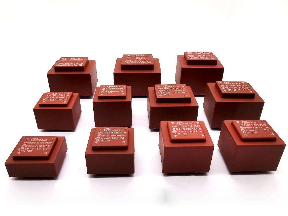
Konwersja mocy stanowi rdzeń nowoczesnych systemów elektronicznych, a Transformatory PCB odgrywają kluczową rolę w zapewnianiu stabilnej i niezawodnej transformacji napięcia bezpośrednio na płytach obwodów drukowanych. Te kompaktowe elementy przekształcają prąd przemienny z jednego poziomu napięcia na inny, zachowując przy tym izolację elektryczną pomiędzy obwodami pierwotnym i wtórnym. Dla inżynierów projektujących układy sterowania przemysłowego, przyrządy pomiarowe oraz zasilacze, zrozumienie tego, jak transformatory PCB wyroby z tworzyw sztucznych osiągają spójną wydajność w warunkach zmiennej obciążenia, jest kluczowe dla niezawodności i trwałości całego systemu.
Niezawodność przekształcania mocy za pomocą transformatorów PCB zależy od wielu wzajemnie powiązanych czynników, w tym projektu elektromagnetycznego, zarządzania ciepłem, integralności izolacji oraz stabilności mechanicznego zamocowania. W przeciwieństwie do transformatorów montowanych na obudowie, transformatory PCB muszą działać w ograniczeniach przestrzennych i termicznych gęsto upakowanych płytek obwodów drukowanych, jednocześnie wytrzymując wibracje, cyklowanie temperatury oraz naprężenia elektryczne przez cały okres ich eksploatacji. W niniejszym artykule omówione są konkretne mechanizmy i zasady projektowe umożliwiające transformatorom PCB utrzymanie dokładnej konwersji napięcia oraz izolacji elektrycznej w wymagających zastosowaniach przemysłowych.
Zasady projektowania elektromagnetycznego umożliwiające spójną konwersję napięcia
Wybór materiału rdzenia i optymalizacja obwodu magnetycznego
Serdze magnetyczne stanowią podstawę niezawodnej konwersji mocy w transformatorach PCB, kierując strumień magnetyczny między uzwojeniem pierwotnym a wtórnym przy minimalnych stratach. Serdza ze stali laminowanej i serdza ferrytowe to dwa dominujące materiały stosowane przy budowie transformatorów PCB, z których każdy oferuje wyraźne zalety dla określonych zakresów częstotliwości i poziomów mocy. Serdza ze stali laminowanej zapewniają doskonałą wydajność przy częstotliwościach sieciowych wynoszących 50 Hz i 60 Hz, zapewniając wysoką gęstość strumienia nasycenia, co umożliwia kompaktowe konstrukcje przeznaczone do zastosowań wymagających znacznej zdolności obsługi mocy w ograniczonej przestrzeni na płytce.
Serduszka ferrytowe wyróżniają się doskonałą wydajnością w zastosowaniach wysokoczęstotliwościowych i niższymi stratami w rdzeniu w porównaniu do blach stalowych, co czyni je odpowiednimi dla zasilaczy impulsowych oraz aplikacji, w których kluczowe znaczenie ma wydajność. Przepuszczalność magnetyczna materiału rdzenia wpływa bezpośrednio na indukcyjność uzwojenia pierwotnego, która z kolei określa prąd magnesujący pobierany ze źródła. Transformatory PCB zaprojektowane z zastosowaniem odpowiednio dobranych materiałów rdzenia zachowują stabilne wartości indukcyjności w szerokim zakresie temperatur, zapewniając spójną regulację napięcia niezależnie od warunków otoczenia czy zmian obciążenia.
Inżynierowie optymalizują obwód magnetyczny poprzez staranne kontrolowanie pola przekroju rdzenia oraz długości ścieżki magnetycznej, równoważąc potrzebę niskiej reluktancji magnetycznej z ograniczeniami wynikającymi z fizycznych wymiarów urządzenia. Gęstość strumienia magnetycznego musi pozostawać poniżej punktu nasycenia materiału rdzenia we wszystkich warunkach pracy, w tym także podczas chwilowych przeciążeń. W przypadku prawidłowego zaprojektowania, Transformatory PCB utrzymywać liniowe proporcje transformacji napięcia nawet przy zmianie prądu obciążenia od stanu jałowego do pełnej, nominalnej mocy.
Konfiguracja uzwojeń i dokładność stosunku liczby zwojów
Stosunek liczby zwojów między uzwojeniem pierwotnym a wtórnym określa podstawową zależność konwersji napięcia w transformatorach PCB, a dokładność produkcji ma bezpośredni wpływ na dokładność napięcia wyjściowego. Każdy zwój przewodu przyczynia się proporcjonalnie do indukowanego napięcia, dlatego precyzyjna liczba zwojów jest kluczowa do spełnienia ścisłych tolerancji napięciowych wymaganych w zastosowaniach pomiarowych i sterowniczych. Nowoczesne, zautomatyzowane urządzenia do nawijania zapewniają spójność pomiędzy poszczególnymi zwijanymi zwojami, minimalizując różnicę jednostkową między poszczególnymi elementami i gwarantując przewidywalną wydajność w całej serii produkcyjnej.
Wybór przekroju przewodu zapewnia równowagę między zdolnością przenoszenia prądu a stratami miedziowymi oraz wykorzystaniem okna uzwojenia. Grubsze przewodniki zmniejszają straty rezystancyjne i spadki napięcia pod obciążeniem, ale zajmują więcej miejsca w dostępnym obszarze uzwojenia. Transformatory PCB zoptymalizowane pod kątem niezawodności wykorzystują przekroje przewodów zapewniające temperaturę miedzi znacznie poniżej granicznych wartości dopuszczalnych dla izolacji nawet podczas długotrwałej pracy przy znamionowym obciążeniu. Ten zapas termiczny zapobiega stopniowemu pogarszaniu się izolacji, które mogłoby zagrozić niezawodności w długim okresie użytkowania.
Technika uzwojenia ma istotny wpływ na indukcyjność wyciekową, która reprezentuje strumień magnetyczny sprzężony wyłącznie z jednym uzwojeniem, a nie między uzwojeniem pierwotnym a wtórnym. Uzwojenia naprzemienne, w których warstwy pierwotne i wtórne są naprzemiennie ułożone, zmniejszają indukcyjność wyciekową w porównaniu do oddzielnych grup uzwojeń pierwotnych i wtórnych. Niższa indukcyjność wyciekowa poprawia regulację napięcia pod obciążeniem oraz zmniejsza szczyty napięcia podczas przejść przełącznikowych – oba te czynniki przyczyniają się do niezawodnej konwersji mocy w praktycznych zastosowaniach obwodów.
Strategie zarządzania temperaturą w celu zapewnienia trwałej wydajności
Mechanizmy generowania ciepła oraz ścieżki odprowadzania ciepła
Transformatory PCB generują ciepło za pośrednictwem dwóch głównych mechanizmów: strat miedziowych w uzwojeniach spowodowanych nagrzewaniem rezystancyjnym oraz strat rdzenia wynikających z histerezy i prądów wirowych w materiale magnetycznym. Całkowita rozpraszana moc wzrasta wraz ze wzrostem prądu obciążenia i musi być odprowadzana poprzez przewodzenie do płytki obwodu drukowanego, konwekcję do otaczającego powietrza oraz promieniowanie cieplne w kierunku sąsiednich komponentów. Opór cieplny pomiędzy rdzeniem transformatora a powierzchnią montażową staje się kluczowym parametrem projektowym, który określa wartość wzrostu temperatury roboczej względem temperatury otoczenia.
Płyta obwodów drukowanych sama w sobie działa jako radiator dla transformatorów montowanych powierzchniowo, odprowadzając ciepło od elementu za pośrednictwem śladów miedzianych i wewnętrznych płaszczyzn uziemienia. Projektanci płytek zwiększają odprowadzanie ciepła, zapewniając wystarczającą powierzchnię miedzi pod footprintami montażowymi transformatorów oraz stosując otwory termiczne (thermal vias), które przekazują ciepło do warstw płytki położonych po przeciwnej stronie. Wielowarstwowe płytki z dedykowanymi płaszczyznami termicznymi zapewniają lepsze rozpraszanie ciepła niż proste konstrukcje dwuwarstwowe, umożliwiając wyższą gęstość mocy bez wpływu na niezawodność transformatorów.
Chłodzenie konwekcyjne staje się coraz bardziej istotne w miarę wzrostu mocy transformatorów powyżej 5–10 watów. Chłodzenie naturalną konwekcją opiera się na przepływie powietrza wywołanym różnicami gęstości wokół obudowy transformatora, podczas gdy chłodzenie wymuszoną cyrkulacją powietrza za pomocą wentylatorów znacznie poprawia współczynniki przenoszenia ciepła. Transformatory montowane na płytach obwodów drukowanych (PCB), zainstalowane w szczelnych obudowach bez wymuszonej wentylacji, działają w trudniejszych warunkach termicznych i wymagają ostrożnego obniżenia mocy (deratingu), aby zachować dopuszczalne zapasy temperatury. Modelowanie termiczne w fazie projektowania pomaga inżynierom przewidywać temperatury punktów gorących oraz potwierdzać, że materiały izolacyjne pozostają w granicach swoich deklarowanych klas temperaturowych.
Wpływ temperatury na parametry elektryczne i czas życia
Temperatura pracy bezpośrednio wpływa na cechy elektryczne i przewidywany czas eksploatacji transformatorów PCB poprzez wiele mechanizmów fizycznych. Opór uzwojeń wzrasta wraz ze wzrostem temperatury zgodnie z dodatnim współczynnikiem temperaturowym miedzi, zwykle wynoszącym około 0,4% na stopień Celsjusza. Ten wzrost oporu powoduje dodatkowy spadek napięcia pod obciążeniem w warunkach podwyższonej temperatury, co wpływa na wydajność regulacji napięcia. Inżynierowie uwzględniają ten efekt, określając granice regulacji napięcia przy maksymalnej dopuszczalnej temperaturze pracy, a nie w warunkach otoczenia.
Materiały izolacyjne ulegają przyspieszonemu starzeniu w podwyższonej temperaturze zgodnie z zależnością Arrheniusa, zgodnie z którą szybkość degradacji chemicznej wzrasta mniej więcej dwukrotnie przy każdym wzroście temperatury o 10 °C. Transformatory PCB przeznaczone do systemów izolacji klasy A mogą pracować ciągle w temperaturze 105 °C, natomiast systemy klasy B pozwalają na pracę w temperaturze 130 °C. Eksploatacja transformatorów w znacznie niższych temperaturach niż dopuszczalna temperatura izolacji wydłuża przewidywaną żywotność użytkową – od dziesiątek tysięcy godzin do kilkudziesięciu lat – co ma kluczowe znaczenie dla sprzętu przemysłowego zaprojektowanego na okres eksploatacji wynoszący od 20 do 30 lat.
Charakterystyka strat rdzenia zmienia się w sposób złożony wraz ze zmianą temperatury, w zależności od składu materiału magnetycznego. Rdzenie ferrytowe zwykle wykazują wzrost strat przy podwyższonych temperaturach, podczas gdy niektóre gatunki blach transformatorowych charakteryzują się stosunkowo stabilną wydajnością w szerokim zakresie temperatur. Transformatory PCB przeznaczone do zastosowań wymagających wysokiej niezawodności są wyposażone w funkcje ochrony termicznej, takie jak bezpieczniki termiczne lub czujniki temperatury, które zapobiegają pracy poza bezpiecznymi granicami termicznymi, chroniąc zarówno transformator, jak i otaczające go obwody przed uszkodzeniem termicznym w przypadku awarii.
Izolacja elektryczna i integralność izolacji
Wytrzymałość napięciowa i marginesy bezpieczeństwa
Izolacja elektryczna pomiędzy uzwojeniem pierwotnym a wtórnym stanowi podstawowy wymóg bezpieczeństwa i funkcjonalności transformatorów PCB w zastosowaniach konwersji mocy. System izolacji musi wytrzymać nie tylko normalną różnicę napięć roboczych, ale także przejściowe przepięcia wynikające z wyładowań piorunowych, przełączeń oraz wyładowań elektrostatycznych. Normy branżowe określają napięcia prób dielektrycznych zwykle w zakresie od 1,5 do 4,0-krotności znamionowego napięcia izolacji, stosowane przez jedną minutę bez przebicia ani nadmiernego prądu upływu.
Fizyczna odległość między uzwojeniem pierwotnym a wtórnym określa główną barierę izolacyjną w transformatorach PCB, przy czym warstwy taśmy izolacyjnej lub uformowane bariery zapewniają dodatkową wytrzymałość dielektryczną. Odległość przeskokowa wzdłuż powierzchni obudowy transformatora musi spełniać minimalne wartości określone w normach bezpieczeństwa, zależne od napięcia roboczego oraz stopnia zanieczyszczenia środowiska eksploatacyjnego. Transformatory PCB przeznaczone do zastosowania w środowiskach przemysłowych, w których istnieje ryzyko zanieczyszczenia, wymagają większej odległości przeskokowej niż te stosowane w czystych środowiskach biurowych, aby zapobiec przeskokowi powierzchniowemu i ostatecznemu uszkodzeniu izolacji.
Badania wyładowań cząstkowych ujawniają początkowe osłabienia izolacji zanim dojdzie do jej całkowitego przebicia, umożliwiając producentom weryfikację odporności układu izolacyjnego. Transformatory PCB pracujące przy napięciach powyżej 300 V podlegają zwykle badaniom wyładowań cząstkowych w ramach badań typowych, aby potwierdzić, że napięcie zapłonu korony pozostaje bezpiecznie powyżej poziomów naprężeń roboczych. Brak aktywności wyładowań cząstkowych oznacza, że naprężenia pola elektrycznego pozostają w granicach bezpiecznych, co wspiera długotrwałą integralność izolacji przez cały okres eksploatacji transformatora.
Wykonanie izolacji w warunkach obciążeń środowiskowych
Czynniki środowiskowe, w tym wilgotność, cyklowanie temperatury oraz zanieczyszczenia atmosferyczne, z czasem stwarzają wyzwania dla systemów izolacji w transformatorach PCB. Wchłanianie wilgoci obniża wytrzymałość dielektryczną organicznych materiałów izolacyjnych oraz przyspiesza korozję elektrochemiczną przewodników w punktach napięciowego obciążenia. Powłoka ochronna (conformal coating) naniesiona na zmontowany transformator stanowi barierę ochronną przed przedostawaniem się wilgoci i zanieczyszczeń, co jest szczególnie istotne dla urządzeń działających w środowiskach zewnętrznych lub przemysłowych o wysokiej wilgotności.
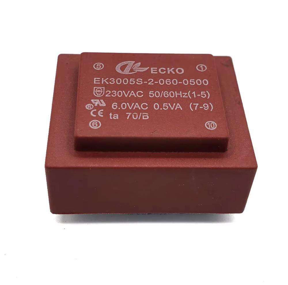
Cyklowanie termiczne powoduje naprężenia mechaniczne na granicach materiałów z powodu różnic współczynników rozszerzalności cieplnej między przewodnikami miedzianymi, materiałami izolacyjnymi i rdzenie magnetyczne powtarzające się rozszerzanie i kurczenie mogą powodować powstawanie mikropęknięć w warstwach izolacji, które stopniowo się rozprzestrzeniają pod wpływem naprężeń elektrycznych. Transformatory PCB przeznaczone do zastosowań motocyklowych lub zewnętrznych poddawane są przyspieszonemu testowaniu trwałości z wielokrotnymi cyklami temperatur obejmującymi cały zakres roboczy, aby zweryfikować integralność mechaniczną systemu izolacji w realistycznych warunkach obciążenia.
Wysokość nad poziomem morza wpływa na wydajność izolacji poprzez obniżone ciśnienie atmosferyczne, co zmniejsza wytrzymałość dielektryczną szczelin powietrznych w konstrukcji transformatora. Urządzenia zaprojektowane do pracy na wysokości powyżej 2000 m wymagają albo zwiększenia odstępów izolacyjnych, albo uszczelnienia hermetycznego, aby zachować wydajność izolacji równoważną tej uzyskiwanej przy pracy na poziomie morza. Certyfikaty bezpieczeństwa dla transformatorów PCB zwykle określają maksymalną dopuszczalną wysokość pracy lub wymagają czynników obniżenia mocy (derating) przy instalacjach na dużych wysokościach, aby zapewnić ciągłą zgodność z wymaganiami dotyczącymi izolacji.
Zagadnienia związane z stabilnością mechaniczną i montażem
Metody montażu płytek PCB oraz niezawodność połączeń lutowanych
Mechaniczny interfejs między transformatorami PCB a płytą obwodu bezpośrednio wpływa zarówno na integralność połączeń elektrycznych, jak i na wydajność rozpraszania ciepła. Montaż przelotowy z zaciskami wprowadzanymi przez metalizowane otwory i lutowanymi po przeciwnej stronie zapewnia solidne mocowanie mechaniczne oraz doskonałe sprzężenie termiczne z płytą. Masa transformatorów PCB, wahająca się od kilku gramów do ponad 100 gramów dla jednostek o wyższej mocy, generuje znaczące naprężenia w złączach lutowanych podczas wibracji i wstrząsów, co czyni odpowiednie zaprojektowanie mocowania kluczowym dla długoterminowej niezawodności.
Średnica, długość i odstęp pinów muszą dokładnie odpowiadać wzorowi otworów na płytce, aby uniknąć naprężeń mechanicznych podczas montażu. Zbyt grube piny powodują połączenia wciskane, które mogą uszkodzić otwory metalizowane, podczas gdy zbyt cienkie piny prowadzą do słabszych połączeń lutowanych o wysokim oporze cieplnym. Transformatory PCB przeznaczone do zastosowań przemysłowych często zawierają wiele pinów uziemiających lub pinów montażowych zapewniających stabilność mechaniczną niezależnie od połączeń elektrycznych, rozprowadzając obciążenia mechaniczne na kilka punktów kotwienia zamiast obciążać połączenia przenoszące prąd.
Jakość połączeń lutowanych ma bezpośredni wpływ zarówno na przewodność elektryczną, jak i na przewodzenie ciepła od zacisków transformatora do miedzi płytki PCB. Procesy lutowania falowego i selektywnego muszą zapewniać pełne zwilżenie oraz prawidłowe uformowanie brzegów lutu wokół pinów transformatora, bez powstawania mostków lutowniczych między blisko położonymi zaciskami. Masa termiczna transformatorów montowanych na płytach PCB wymaga starannego doboru profilu nagrzewania wstępnego, aby doprowadzić cały komponent do temperatury lutowania bez ryzyka szoku termicznego dla wewnętrznych materiałów izolacyjnych lub rdzeni magnetycznych.
Odporność na wibracje i kontrola hałasu akustycznego
Transformatory PCB montowane na płytach obwodów drukowanych podlegają wibracjom pochodzącym ze źródeł zewnętrznych, takich jak silniki, wentylatory i transport, a także siłom generowanym wewnętrznie przez zjawisko magnetostrykcji w materiale rdzenia. Magnetostrykcja powoduje zmiany wymiarów materiału rdzenia zsynchronizowane z przemiennym polem magnetycznym, generując szum akustyczny o częstotliwości podstawowej oraz jej harmonicznych. Choć amplituda zjawiska magnetostrykcji jest niewielka, duża powierzchnia rdzenia oraz konstrukcji montażowej mogą wzmacniać emisję akustyczną do poziomów stających się uciążliwe w sprzęcie konsumenckim i biurowym.
Hermetyzacja lub wlewanie transformatorów PCB za pomocą związków epoksydowych lub poliuretanowych zapewnia wiele korzyści, w tym tłumienie drgań, ochronę przed wilgocią oraz redukcję hałasu akustycznego. Materiał hermetyzujący tworzy mechaniczne połączenie pomiędzy warstwami rdzenia, co zmniejsza amplitudę drgań i tłumi rezonansowe mody wzmacniające emisję akustyczną. Jednakże hermetyzacja ogranicza również wymianę ciepła przez konwekcję z powierzchni transformatora, dlatego wymagana jest staranna analiza termiczna, aby zapewnić, że temperatury robocze pozostają na akceptowalnym poziomie mimo wzrostu impedancji cieplnej.
Urządzenia narażone na wysokie poziomy wibracji, takie jak zastosowania w przemyśle motocyklowym, kolejowym i przemysłowym, wymagają transformatorów PCB specjalnie zaprojektowanych i przetestowanych pod kątem odporności na wibracje. Dodatkowe cechy mechanicznego montażu, takie jak uchwyty podstawy lub klejenie adhezyjne, uzupełniają połączenia lutowane, aby zapobiec awariom zmęczeniowym podczas długotrwałego narażenia na wibracje. Testy kwalifikacyjne zgodne ze standardami motocyklowymi, np. AEC-Q200, lub standardami kolejowymi, obejmującymi impulsy udarowe i losowe widma wibracji, potwierdzają wytrzymałość mechaniczną przed wprowadzeniem produktu do produkcji.
Kontrola jakości i walidacja długotrwałej niezawodności
Testy produkcyjne i weryfikacja parametrów
Kompleksowe testy elektryczne przeprowadzane w trakcie produkcji zapewniają, że każdy transformator PCB spełnia określone parametry wydajności przed integracją do zespołów obwodów. Zautomatyzowane wyposażenie pomiarowe mierzy stosunek uzwojeń, indukcyjność pierwotną, indukcyjność wyciekową, opór uzwojeń oraz opór izolacji we 100% jednostek produkcyjnych. Te testy parametryczne wykrywają wady produkcyjne, takie jak zwarcia w uzwojeniach, nieprawidłowa liczba zwojów lub uszkodzenia izolacji, które mogłyby zagrozić niezawodnością w trakcie eksploatacji.
Test hipot polega na przyłożeniu wysokiego napięcia między odizolowanymi uzwojeniami oraz między uzwojeniami a rdzeniem, aby zweryfikować integralność izolacji bez uszkadzania systemu izolacyjnego. Poziomy napięcia testowego i czas jego przyłożenia są starannie kontrolowane, aby uniknąć nadmiernego obciążenia izolacji, jednocześnie zapewniając wystarczający margines bezpieczeństwa. Transformatory PCB, które pomyślnie przejdą test hipot, potwierdzają, że ich systemy izolacyjne są w stanie wytrzymać napięcia robocze oraz oczekiwane przejściowe przepięcia występujące w całym okresie ich eksploatacji.
Testy wzrostu temperatury na reprezentatywnych próbkach potwierdzają wydajność cieplną w warunkach obciążenia znamionowego. Transformatory są eksploatowane przy napięciu i prądzie obciążenia znamionowego aż do ustabilizowania się temperatur, po czym pomiary temperatury punktów gorących wykonuje się za pomocą termopar lub obrazowania podczerwonego. Dane dotyczące wzrostu temperatury potwierdzają, że zapasy projektowe w zakresie wydajności cieplnej są wystarczające oraz że transformator może pracować w sposób ciągły przy obciążeniu znamionowym bez przekraczania klasyfikacji temperaturowych izolacji. Testy te pozwalają zidentyfikować potencjalne słabe punkty projektu cieplnego przed wprowadzeniem produktu do produkcji.
Przyspieszone testy trwałości i analiza trybów uszkodzeń
Przyspieszone testy trwałości poddają transformatory PCB działaniu podwyższonej temperatury, wilgotności oraz naprężeń elektrycznych, aby w skróconym czasie osiągnąć efekt równoważny starzeniu się. Testy trwałości w wysokiej temperaturze polegają na eksploatacji transformatorów w warunkach maksymalnej dopuszczalnej temperatury przez tysiące godzin i służą weryfikacji długowieczności układu izolacyjnego oraz identyfikacji potencjalnych mechanizmów uszkodzenia. Okresowe pobieranie próbek testowych w celu pomiaru parametrów elektrycznych pozwala śledzić tendencje degradacji oraz prognozować kryteria końca życia na podstawie dopuszczalnych granic zmian tych parametrów.
Połączone testy temperatury i wilgotności narażają transformatory PCB na realistyczne obciążenia środowiskowe, które symulują lata eksploatacji w terenie w skondensowanych cyklach testowych. Testy te ujawniają podatność na degradację spowodowaną wilgocią, w tym korozję, osłabienie izolacji oraz zmiany wymiarowe materiałów. Transformatory, które przejdą rygorystyczne testy środowiskowe, wykazują odporną konstrukcję, odpowiednią do wdrożenia w trudnych środowiskach przemysłowych bez dodatkowych obudów ochronnych.
Analiza trybów awarii i ich skutków w trakcie rozwoju produktu identyfikuje potencjalne mechanizmy awarii oraz ich skutki dla działania systemu. Cechy konstrukcyjne zapobiegające awariom jednopunktowym lub zapewniające tryby łagodnego obniżenia wydajności zwiększają ogólną niezawodność systemu. Na przykład transformatory PCB wyposażone w bezpieczniki termiczne, które otwierają obwód pierwotny w przypadku przekroczenia temperatury roboczej, zapobiegają katastrofalnym trybom awarii, takim jak przebicie izolacji lub spalenie uzwojeń, które mogłyby uszkodzić otaczającą elektronikę lub stworzyć zagrożenia bezpieczeństwa.
Często zadawane pytania
Co decyduje o zdolności transformatorów PCB do obsługi mocy?
Moc, jaką mogą przetwarzać transformatory PCB, zależy od powierzchni przekroju rdzenia, która określa granice gęstości strumienia magnetycznego, oraz od powierzchni okna uzwojenia dostępnej na przewodniki, która decyduje o zdolności przenoszenia prądu. Możliwość odprowadzania ciepła stanowi ostateczny limit ciągłej mocy przetwarzanej, ponieważ temperatury pracy muszą pozostawać w granicach dopuszczalnych dla systemu izolacji. Większe wymiary rdzenia oraz grubsze przewody pozwalają na wyższe klasyfikacje mocy, jednak ograniczenia związane z fizycznymi rozmiarami płytek obwodów drukowanych często wymagają kompromisów między mocą a powierzchnią zajmowaną przez element.
W jaki sposób transformatory PCB zapewniają stabilizację napięcia przy zmieniających się obciążeniach?
Regulacja napięcia w transformatorach PCB zależy przede wszystkim od oporu uzwojeń i indukcyjności wyciekowej, które powodują spadki napięcia proporcjonalne do prądu obciążenia. Poprawnie zaprojektowane transformatory PCB minimalizują te impedancje pasożytnicze dzięki odpowiedniemu doborowi przekroju przewodników oraz zoptymalizowanym układom uzwojeń, maksymalizującym sprzężenie magnetyczne między uzwojeniem pierwotnym a wtórnym. Typowa regulacja napięcia w wysokiej jakości transformatorach PCB mieści się w zakresie od 5% do 15% przy przejściu od stanu jałowego do pełnego obciążenia; lepsza regulacja osiągana jest w konstrukcjach zoptymalizowanych pod kątem niskich strat miedziowych oraz minimalnej indukcyjności wyciekowej.
Czy transformatory PCB mogą działać niezawodnie w środowiskach o wysokiej temperaturze?
Transformatory PCB mogą działać niezawodnie w środowiskach o wysokiej temperaturze, pod warunkiem ich prawidłowego doboru z uwzględnieniem odpowiednich klas temperaturowych izolacji oraz wystarczającego obniżenia mocy ze względu na ograniczenia termiczne. Transformatory z systemami izolacji klasy B lub F pozwalają na temperatury otoczenia odpowiednio do 130 °C lub 155 °C, jednak moc musi zostać obniżona (derated), aby zachować akceptowalne zapasy temperatury przekroczonych w stosunku do temperatury otoczenia. Przemysłowe transformatory PCB przeznaczone do ciągłej pracy w warunkach podwyższonej temperatury otoczenia charakteryzują się ostrożnymi zapasami projektowymi w zakresie odporności termicznej oraz materiałami izolacyjnymi odpornymi na wysokie temperatury, które zachowują swoje właściwości dielektryczne i mechaniczne nawet przy długotrwałym narażeniu na działanie ciepła.
Jakie praktyki konserwacyjne wydłużają czas użytkowania transformatorów PCB?
Transformatory PCB są zazwyczaj elementami nie wymagającymi konserwacji, jednak praktyki stosowane na poziomie systemu znacząco wpływają na ich żywotność eksploatacyjną. Zapewnienie odpowiedniej wentylacji oraz utrzymanie temperatury otoczenia w granicach określonych w specyfikacji zapobiega przyspieszonemu starzeniu się izolacji. Ochrona transformatorów przed wilgocią, zanieczyszczeniami oraz atmosferami korozyjnymi poprzez odpowiednie zaprojektowanie obudowy zachowuje integralność izolacji. Unikanie pracy poza zakresem określonym dla napięcia i prądu znamionowego zapobiega powstawaniu uszkodzeń wynikających z nagromadzonego naprężenia. W zastosowaniach krytycznych okresowe badania termograficzne w podczerwieni pozwalają wykryć nietypowy wzrost temperatury, który może wskazywać na rozwijające się problemy jeszcze przed wystąpieniem awarii, umożliwiając proaktywną wymianę w ramach zaplanowanych okresów konserwacji zamiast nieplanowanego przestoju.
Spis treści
- Zasady projektowania elektromagnetycznego umożliwiające spójną konwersję napięcia
- Strategie zarządzania temperaturą w celu zapewnienia trwałej wydajności
- Izolacja elektryczna i integralność izolacji
- Zagadnienia związane z stabilnością mechaniczną i montażem
- Kontrola jakości i walidacja długotrwałej niezawodności
-
Często zadawane pytania
- Co decyduje o zdolności transformatorów PCB do obsługi mocy?
- W jaki sposób transformatory PCB zapewniają stabilizację napięcia przy zmieniających się obciążeniach?
- Czy transformatory PCB mogą działać niezawodnie w środowiskach o wysokiej temperaturze?
- Jakie praktyki konserwacyjne wydłużają czas użytkowania transformatorów PCB?