Why OEM Buyers Choose ECKO for Waterproof Transformer Projects
Application-Based Engineering
We review the load type, duty cycle, cable distance, ambient temperature, installation zone and target safety requirements before finalizing the transformer. This helps avoid incorrect VA selection, excessive temperature rise and unstable output voltage.
Electrical and Mechanical Design in One Project
The transformer winding, magnetic core, enclosure, resin, cable gland and mounting structure are developed as one complete assembly. This is especially important when IP protection and thermal performance must be achieved at the same time.
Controlled Design Documentation
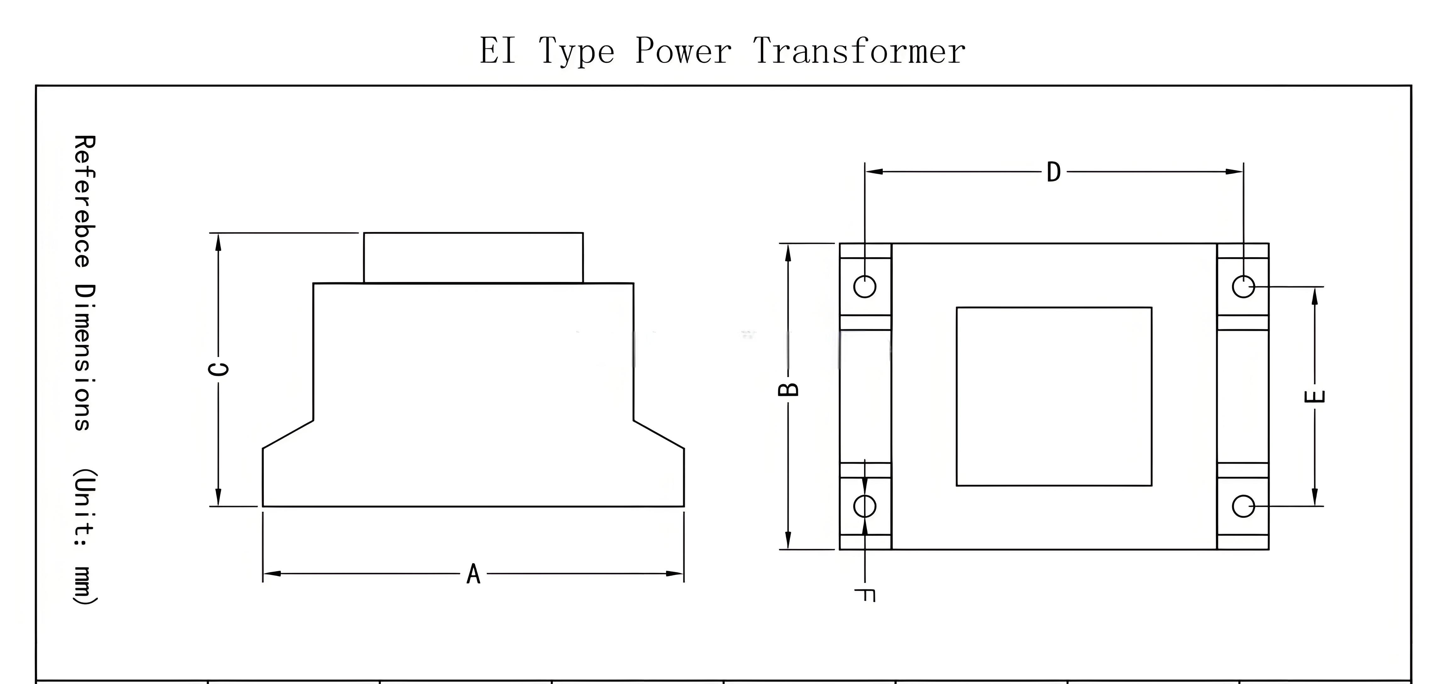
Input, output, wire size, protection components, dimensions, cable pinout and label information are recorded in the approved drawing. Engineering changes can therefore be reviewed and controlled before they enter production.
Waterproofing Beyond an Outer Coating
A reliable waterproof design depends on the resin, housing, cable jacket, cable entry, strain relief, curing process and installation method. ECKO evaluates these details instead of relying only on an external waterproof label.
Prototype and Production Capability
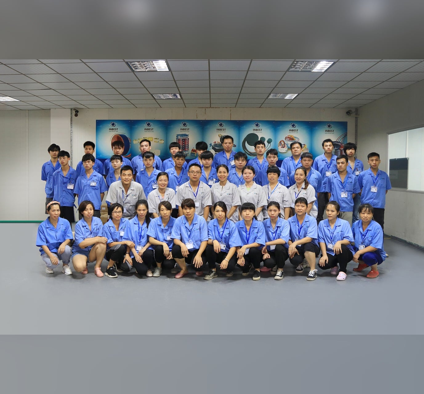
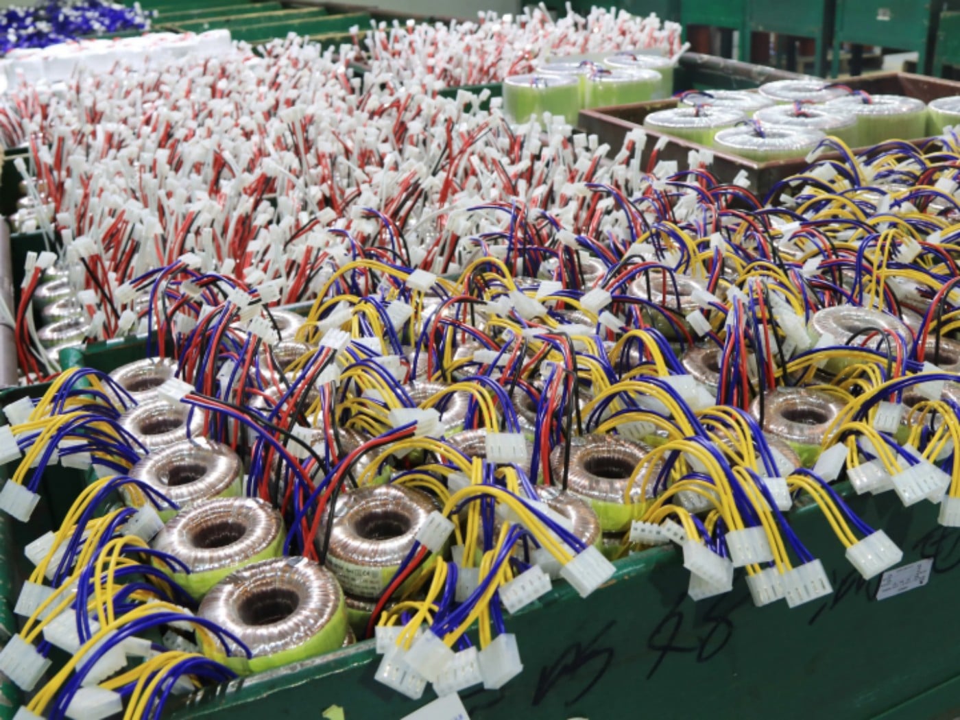
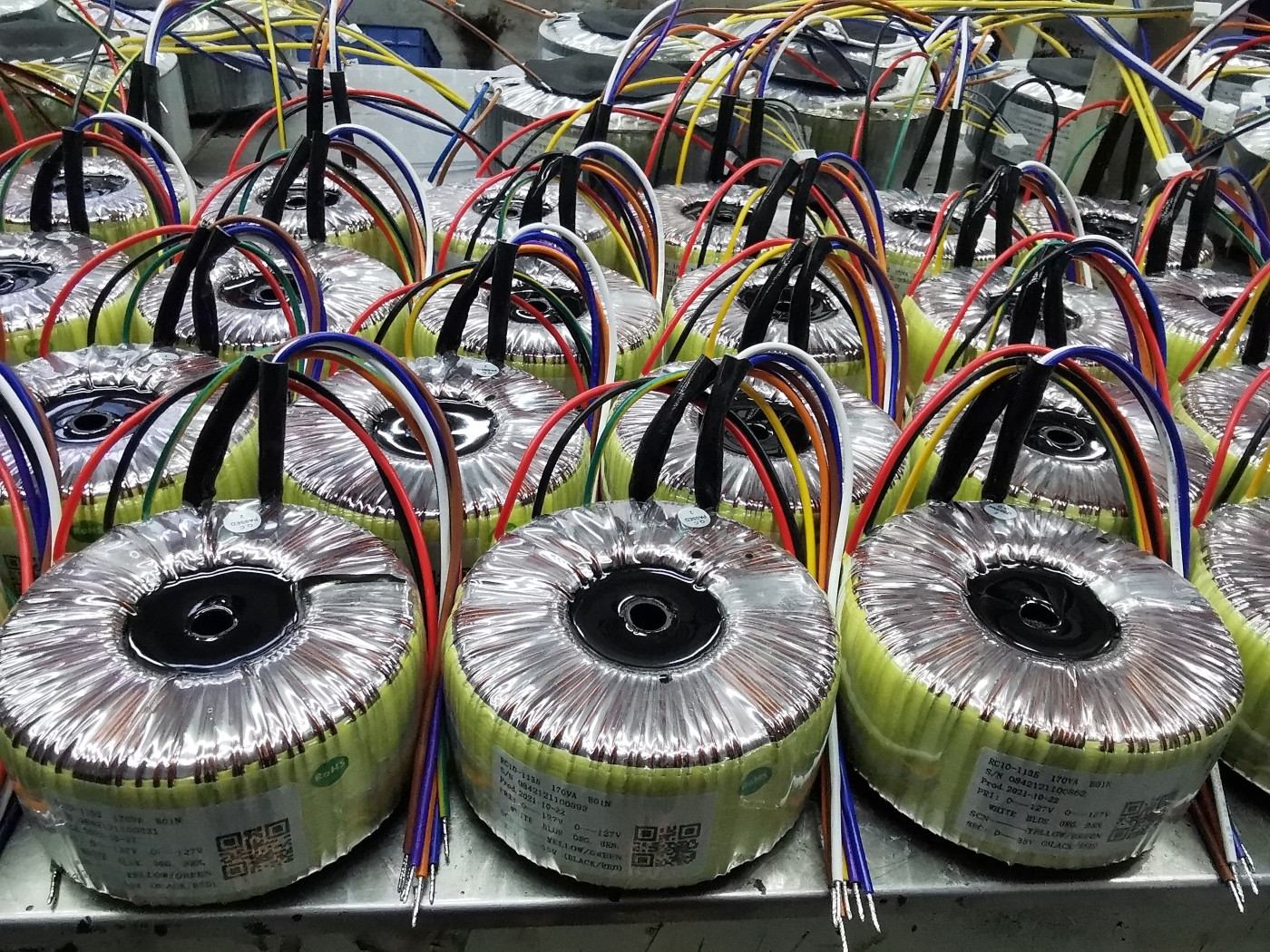
Established in 2000, ECKO operates three workshops covering approximately 5,000 square metres with 150 skilled workers and annual capacity of around one million wound-component Products Prototype lead time can be as fast as 1–3 days when the required materials are available.
Technical Support from Sample to Mass Production
Customers can confirm electrical performance, dimensions, cable assembly, label and installation fit with a prototype before production. Inspection requirements and project-specific test reports can be agreed during sample approval.
Quality Testing
Waterproof Transformer Inspection and Validation
Routine electrical tests and design-validation tests serve different purposes. The final test limits and inspection frequency should be recorded in the approved specification or Control Plan.
| Test Item |
Purpose |
Recommended Frequency |
| Visual and Dimensional Inspection |
Confirms housing, label, cable, mounting and workmanship |
100% |
| Winding Continuity |
Detects open circuits and incorrect connections |
100% |
| Turns Ratio / No-Load Voltage |
Confirms input-to-output voltage ratio |
100% |
| No-Load Current |
Checks magnetic design and assembly consistency |
Routine or agreed sampling |
| Winding Resistance |
Verifies winding consistency and conductor condition |
Routine or agreed sampling |
| Hi-Pot Test |
Verifies dielectric isolation between windings and accessible parts |
100% when included in the approved Control Plan |
| Insulation Resistance |
Checks insulation condition and moisture-related leakage |
Routine or agreed sampling |
| Ground Continuity |
Confirms protective earth connection on applicable metal housings |
100% where applicable |
| Load Voltage Test |
Confirms output voltage under the specified load |
Sample and lot verification |
| Temperature-Rise Test |
Validates thermal performance at rated load and ambient condition |
Design validation or type test |
| Thermal Protector Test |
Confirms the selected protector and trip requirements |
Component and sample verification |
| IP / Water-Ingress Test |
Validates the complete enclosure and cable-entry design |
Type test or project-defined sampling |
| Potting and Curing Inspection |
Checks resin fill, surface condition and curing consistency |
Visual inspection plus batch control |
| Final Functional Test |
Confirms correct wiring, polarity and operating performance |
100% or agreed Control Plan |
Quality Statement:
Every shipment follows the approved product specification. Test records, inspection reports or project-specific validation data can be discussed during the quotation and sample-approval stage.
From Application Requirements to Production-Ready Waterproof Transformer
Step 1 — Application Review
Send the input voltage, output voltage, rated current, load type, cable distance, ambient temperature, IP requirement and installation information.
Step 2 — Engineering Evaluation
ECKO evaluates transformer capacity, winding design, voltage regulation, temperature rise, insulation, protection components, enclosure and cable assembly.
Step 3 — Quotation and Drawing
You receive a commercial quotation together with the proposed electrical and mechanical specification. Key parameters are confirmed before prototype production.
Step 4 — Prototype Manufacturing
A custom sample is manufactured using the agreed materials and construction. Sample lead time can be as fast as 1–3 days for suitable projects with available materials.
Step 5 — Sample Verification
The customer checks electrical performance, dimensions, mounting, cable connections and operation with the actual equipment. Any required changes are reviewed before approval.
Step 6 — Pilot Run and Mass Production
After sample approval, production follows the confirmed drawing, materials and inspection requirements. A pilot quantity can be arranged when additional validation is required.
Step 7 — Final Inspection and Delivery
Finished products are inspected and packed according to the agreed specification. Carton, pallet, private-label packaging and export documentation can be customized.
Outdoor Waterproof Transformer FAQ
1. What makes a transformer suitable for outdoor garden or swimming pool lighting?
The transformer should provide appropriate electrical isolation, moisture protection, temperature resistance and stable low-voltage output. Its enclosure, potting material, cables and connectors must be selected according to the actual installation environment.
2. Is a safety isolation transformer required for swimming pool lights?
Many pool-lighting systems require a safety-isolating transformer to separate the low-voltage lighting circuit from the mains supply. The required output voltage, installation position and protective measures must comply with the regulations applicable to the destination market.
3. Does an IP67 rating mean the transformer can operate permanently underwater?
IP67 normally indicates protection against temporary immersion under specified test conditions. It does not automatically approve the transformer for permanent underwater operation. Direct-submersion applications require a product specifically designed and verified for that purpose.
4. What is the difference between a magnetic transformer and an electronic transformer?
A magnetic transformer uses a laminated or toroidal core and normally provides strong electrical isolation and reliable operation. An electronic transformer uses high-frequency switching technology and may be smaller, but it can have minimum-load and LED compatibility requirements.
5. Can the transformer power LED pool lights with built-in drivers?
If the transformer output voltage, frequency, waveform and available capacity match the LED driver’s input requirements. The LED fixture specification should be reviewed before selecting or designing the transformer.
6. Should an LED lighting transformer be selected only by wattage?
LED fixtures may have startup current, power-factor and driver characteristics that are not fully represented by the nominal wattage. Transformer selection should consider the total operating current, apparent power, startup behavior and required capacity margin.
7. Can one transformer power both outdoor lights and a water pump?
It is generally better to use separate power circuits. Pumps and motors can generate high startup current and electrical disturbances that may cause lighting voltage fluctuations or flickering. If a shared transformer is required, it must be engineered for both load types.
8. Can the transformer have dual primary voltages for different countries?
A transformer can be designed with dual primary windings or selectable input connections, such as 110–120V and 220–240V. The input selection method and wiring instructions must be clearly defined to prevent incorrect connection.
9. Can one transformer provide several independent secondary outputs?
Independent secondary windings can supply separate lighting zones or different output voltages. The voltage, current and insulation requirements of each output should be specified during the design stage.
10. Can two transformer secondary outputs be connected in parallel?
They should not be connected in parallel unless the windings are specifically designed for parallel operation. Small voltage differences can create circulating current, overheating and uneven load sharing. The connection must be confirmed by the transformer manufacturer.
 EN
EN