EN
EN


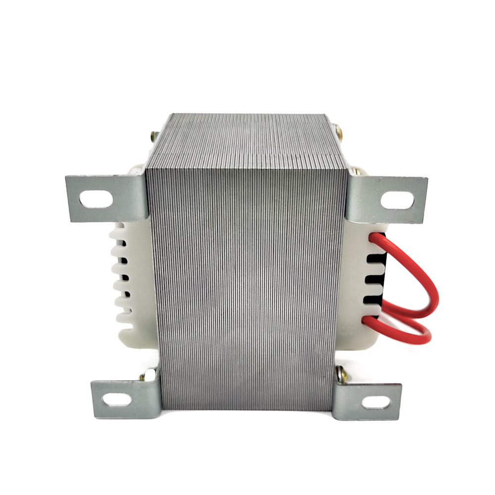
वास्तविक लोड पर आउटपुट की डिज़ाइन की गई है
लक्ष्य द्वितीयक वोल्टेज को संचालन धारा पर परिभाषित किया जाता है, न कि नो-लोड पाठ्यांक से माना जाता है। आवश्यक नियामन प्राप्त करने के लिए वाइंडिंग प्रतिरोध और कोर का आकार संतुलित किया जाता है।
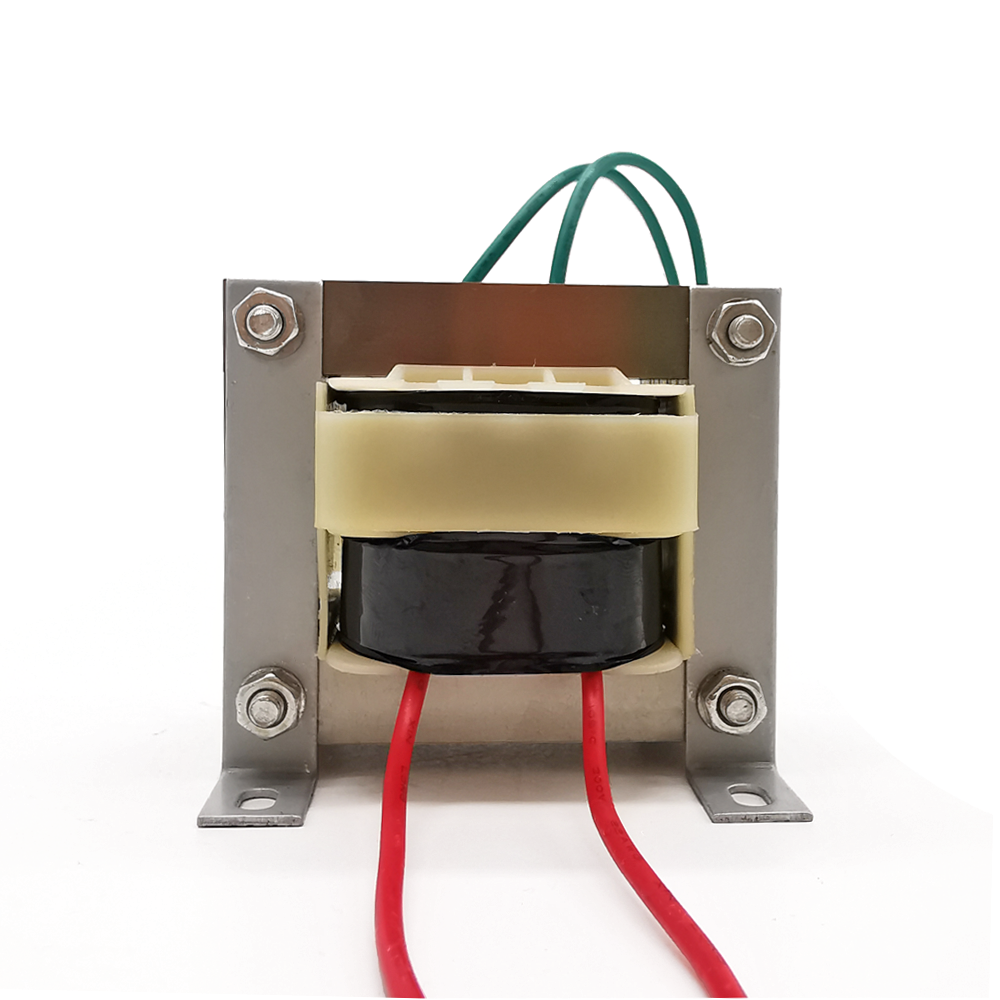
इज़ोलेशन, स्टेप-डाउन और स्टेप-अप के लिए अनुकूलित ट्रांसफॉर्मर, जिनमें एकल, द्वैध, केंद्र-टैप्ड या बहु-द्वितीयक वाइंडिंग्स हो सकती हैं।
| डिज़ाइन प्रकार | नई ओईएम डिज़ाइन, मूल्य-इंजीनियरिंग द्वारा पुनर्डिज़ाइन या फॉर्म-फिट-फंक्शन प्रतिस्थापन |
|---|---|
| विद्युत कार्य | गैल्वेनिक अलगाव, एसी स्टेप-डाउन, एसी स्टेप-अप या गैर-अलगाव ऑटोट्रांसफॉर्मर |
| प्राथमिक वायुधारा | एकल इनपुट, डबल ११५/२३० वी शैली प्राइमरी, कई टैप या ग्राहक-परिभाषित मेन्स रेंज |
| द्वितीयक वाइंडिंग | एक या अधिक एसी आउटपुट; अलग किए गए, सेंटर-टैप्ड या श्रृंखला/समानांतर कनेक्शन |
| शक्ति और आवृत्ति | वीए रेटिंग और ५० हर्ट्ज़, ६० हर्ट्ज़ या ५०/६० हर्ट्ज़ संचालन, जो घोषित लोड और ड्यूटी के लिए गणना किए गए हैं |
| मुख्य निर्माण | लक्ष्य फ्लक्स घनत्व, हानि, आकार और तापमान के लिए चुने गए स्टैक्ड ईआई विद्युत-इस्पात लैमिनेशन |
| कंडक्टर | वर्णित तार के व्यास, वाइंडिंग व्यवस्था और विद्युत रोधन के साथ मिलान किया गया एनामेल्ड तांबे का तार |
| थर्मल डिज़ाइन | परिभाषित वातावरण, तापमान वृद्धि लक्ष्य, विद्युत रोधन श्रेणी, वेंटिलेशन और माउंटिंग अभिविन्यास |
| यांत्रिक प्रारूप | खुला फ्रेम, कवर, अनुकूलित ब्रैकेट, माउंटिंग फीट, पीसीबी प्रारूप या परियोजना-विशिष्ट असेंबली |
| कनेक्शन | फ्लाइंग लीड्स, स्लीव्ड लीड्स, निर्दिष्ट कनेक्टर्स, सोल्डर लग्स, क्विक-कनेक्ट टैब्स, टर्मिनल्स या पीसीबी पिन्स |
| सुरक्षा | आंतरिक तापीय फ्यूज़, रीसेट करने योग्य सुरक्षा उपकरण, बाह्य फ्यूज़ की सिफारिश या अनुप्रयोग-विशिष्ट समाधान |
| वैकल्पिक उपचार | वार्निश अंतःस्राव, विद्युत स्थैतिक स्क्रीन, फ्लक्स शील्डिंग, सुरक्षात्मक कवर या एनकैप्सुलेशन मूल्यांकन |
| नियंत्रित विशेषताएँ | आउटपुट सहिष्णुता, वोल्टेज नियमन, डीसी प्रतिरोध, नो-लोड धारा, नो-लोड हानि, शोर और पारद्युतिक शक्ति |
| परियोजना रेकॉर्ड्स | रूपरेखा और वायरिंग ड्रॉइंग, लेबल कलाकृति, स्वीकृत नमूना, परीक्षण योजना और निरीक्षण रिपोर्ट, जैसा कि सहमति से तय किया गया है |
चूँकि यह एक इंजीनियर-टू-ऑर्डर उत्पाद है, अंतिम ट्रांसफॉर्मर को मंजूर किया गया ड्रॉइंग—एक सामान्य कैटलॉग टेबल नहीं—नियंत्रित करता है। निम्नलिखित पैरामीटर प्रत्येक परियोजना के लिए क्या परिभाषित किया जा सकता है, यह दर्शाते हैं।
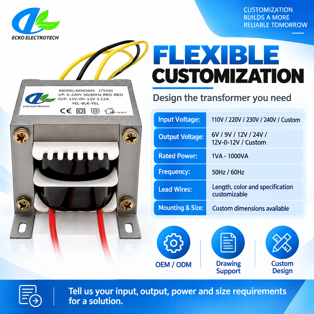
प्रत्येक लाभ के लिए एक क्लोज़-अप छवि का उपयोग करें। समर्थनकारी पाठ जीवित HTML के रूप में बना रहता है, जिससे खरीदारों को छोटे, अपठनीय पाठ से भरे ग्राफ़िक के बिना स्पष्ट जानकारी प्राप्त होती है।
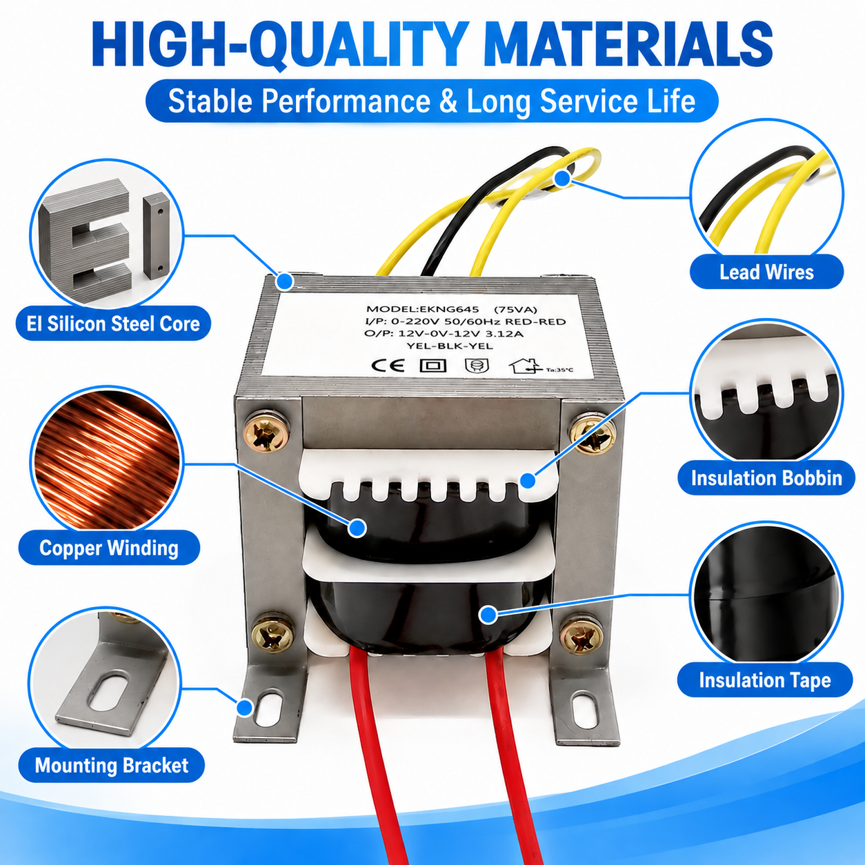
प्रत्येक चयन डिज़ाइन के किसी अन्य भाग को प्रभावित करता है। उदाहरण के लिए, कड़ी नियामकता के लिए अधिक तांबा या बड़ा कोर आवश्यक हो सकता है, जबकि कम ऊँचाई फुटप्रिंट को बढ़ा सकती है। ECKO नमूनाकरण से पहले इन सौदों की समीक्षा करता है।
| स्वयंकृतीकरण क्षेत्र | खरीदार के विकल्प | इंजीनियरिंग प्रभाव |
|---|---|---|
| इनपुट और आवृत्ति | नाममात्र वोल्टेज, सहनशीलता, टैप, डबल प्राथमिक, ५०/६० हर्ट्ज़ | टर्न्स, चुंबकीय प्रवाह घनत्व, विद्युत रोधन और कनेक्शन आरेख निर्धारित करता है |
| आउटपुट | वोल्टेज, आरएमएस धारा, एक साथ लोड, केंद्र टैप, विद्युत अलगाव | वीए, चालक का आकार, वोल्टेज नियमन और ऊष्मीय वितरण निर्धारित करता है |
| भार प्रोफ़ाइल | प्रतिरोधक, रेक्टिफायर-कैपेसिटर, रिले, मोटर, अंतराय या निरंतर | आरएमएस धारा, प्रारंभिक मांग, तांबे की हानि और सुरक्षा रणनीति में परिवर्तन करता है |
| आकार और माउंटिंग | अधिकतम लंबाई × चौड़ाई × ऊँचाई, छिद्र के केंद्र, पिन, पैर, ब्रैकेट और अभिविन्यास | कोर चयन, स्टैक, लीड निकास और असेंबली विधि को नियंत्रित करता है |
| तापीय आवश्यकताएँ | परिवेश तापमान, आवरण, वेंटिलेशन, कार्य चक्र और तापमान वृद्धि सीमा | नियंत्रण सामग्री वर्ग, हानि बजट, डेरेटिंग और मान्यन परीक्षण को निर्धारित करता है |
| टर्मिनेशन | तार का रंग और लंबाई, कनेक्टर, लग, टर्मिनल, पिनआउट और स्लीविंग | असेंबली समय, गलती-रोधी उपायों और ग्राहक स्थापना को प्रभावित करता है |
| सुरक्षा | थर्मल फ्यूज़, रीसेट करने योग्य सुरक्षा या बाहरी सर्किट सुरक्षा | दोष स्थितियों और अंतिम उत्पाद की सुरक्षा डिज़ाइन के साथ समन्वयित होना आवश्यक है |
| शोर और ईएमसी | शोर लक्ष्य, इम्प्रेग्नेशन, इलेक्ट्रोस्टैटिक स्क्रीन या फ्लक्स शील्डिंग | यांत्रिक गुनगुनाहट, कॉमन-मोड कपलिंग, विचरित क्षेत्र, आकार और लागत को प्रभावित करता है |
| अनुपालन रिकॉर्ड | सामग्री घोषणाएँ, परीक्षण रिपोर्ट, एजेंसी आवश्यकताएँ और लेबल | अनुमोदित सामग्री, निर्माण नियंत्रण और प्रलेखन को परिभाषित करता है |
पूर्ण संचालन डेटा भेजने से उद्धरण एक अनुमानित वोल्टेज मिलान के बजाय वास्तविक ट्रांसफॉर्मर को दर्शाता है।
एक अनुभाग का परिचय देने के लिए एक अनुप्रयोग का फोटो होना चाहिए, लेकिन प्रत्येक बाज़ार के लिए अनुक्रमणीय एचटीएमएल पाठ की भी आवश्यकता होती है। यह स्पष्ट करता है कि ट्रांसफॉर्मर क्या संचालित करता है और खरीदार के लिए कौन-सी डिज़ाइन शर्तें महत्वपूर्ण हैं।
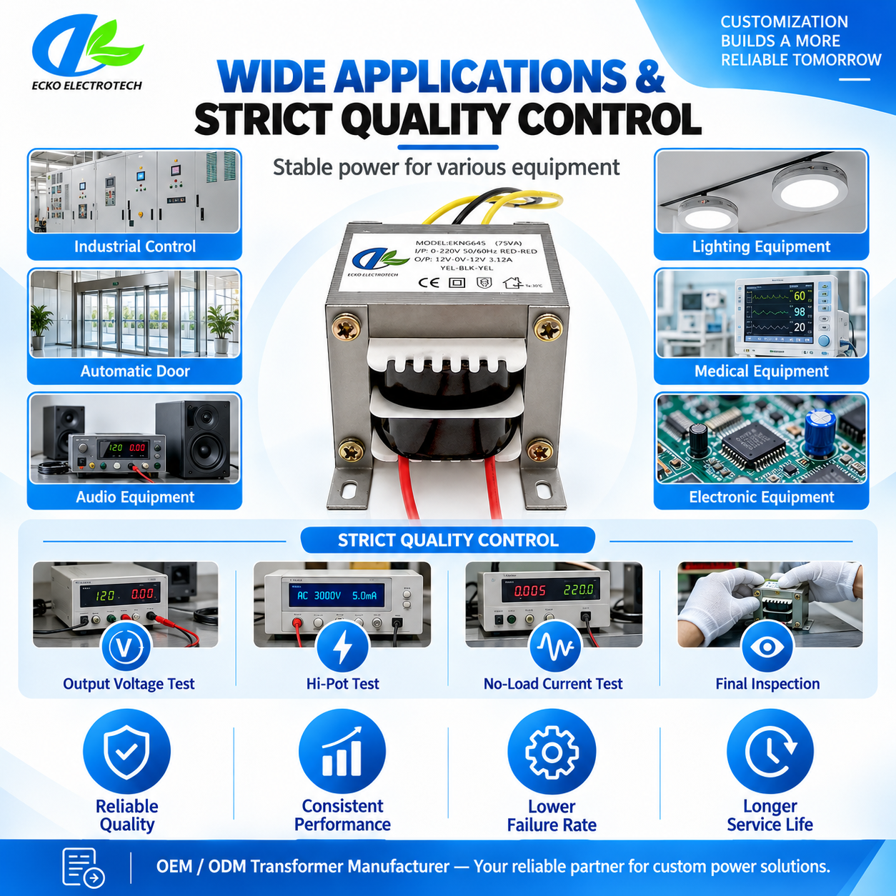
कॉन्टैक्टर्स, रिले, सॉलेनॉइड्स, सूचक परिपथों और सहायक इलेक्ट्रॉनिक्स के लिए अलग किया गया नियंत्रण वोल्टेज प्रदान करें। इनपुट टैप मशीनरी के लिए समर्थन प्रदान कर सकते हैं जो विभिन्न कारखाना मेन्स आपूर्तियों के लिए निर्मित होती हैं।
ऐसे एम्पलीफायर और प्री-एम्पलीफायर रेल्स की आपूर्ति करें जहाँ वाइंडिंग सममिति, चुंबकीय युग्मन, यांत्रिक हम और चैसिस स्थानन इंजीनियरिंग ध्यान की आवश्यकता करते हैं।
शक्ति द्वार नियंत्रक, ताले, सेंसर, इंटरकॉम और अलार्म परिपथ। स्टैंडबाय लोड, लॉक इनरश, एनक्लोज़र तापमान और अनुपालन को एक साथ विचार करना आवश्यक है।
वेंडिंग मशीनों, कॉफी उपकरणों और व्यावसायिक रसोई उपकरणों में नियंत्रण बोर्ड, वाल्व, डिस्प्ले और रिले के लिए कम-वोल्टेज एसी उत्पन्न करें।
मीटर, परीक्षण फिक्सचर और विश्लेषणात्मक उपकरणों के लिए अलग किए गए सहायक रेल बनाएँ। अलग-अलग वाइंडिंग्स एनालॉग, डिजिटल और स्विचिंग लोड के बीच पारस्परिक क्रिया को कम कर सकती हैं।
दोहराए जाने वाले स्विचिंग और लंबे सेवा घंटों के लिए उजागर किए गए नियंत्रण और संकेत परिपथों को आपूर्ति करें। डिज़ाइन को कैबिनेट स्थान, स्थानीय मेन्स वोल्टेज और प्रतिस्थापन आवश्यकताओं के अनुसार समायोजित किया जा सकता है।
पेशेवर ट्रांसफॉर्मर की आपूर्ति तकनीकी आवश्यकताओं के अनुवाद, दस्तावेज़ीकरण और पुनरुत्पादन पर निर्भर करती है। ईको पूरे मंजूरी चक्र का समर्थन करता है—अधूरे उपकरण डेटा से लेकर नियंत्रित उत्पादन विनिर्देश तक।
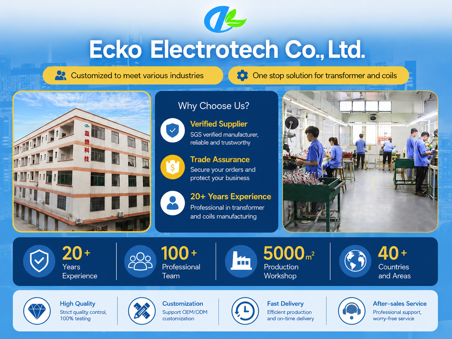
जब कोई खरीदार केवल लोड सर्किट, पीसीबी ड्रॉइंग या पुराना नमूना रखता है, तो ईको डिज़ाइन रिलीज़ से पहले लुप्त विद्युत और यांत्रिक जानकारी की पहचान करता है।
यदि कोई लक्ष्य उपलब्ध स्थान या ऊष्मीय सीमा में फिट नहीं होता है, तो टीम कोर के आकार, नियामन, कवच, विद्युतरोधन या माउंटिंग में परिवर्तन के प्रभाव की व्याख्या करती है।
एक अप्रचलित ट्रांसफॉर्मर का मूल्यांकन वोल्टेज, धारा, वायरिंग, आकार, तापमान, शोर और सुरक्षा के आधार पर किया जाता है—उसके बाहरी आयामों के आधार पर नहीं।
ड्रॉइंग्स, वाइंडिंग निर्देश, सामग्री और स्वीकृति सीमाएँ स्वीकृत प्रोटोटाइप को भविष्य के बैचों से जोड़ती हैं और अदृश्य प्रतिस्थापनों को रोकने में सहायता करती हैं।
सामग्री चयन, परीक्षण फिक्सचर, लेबल और पैकिंग की समावृत्ति को ध्यान में रखकर समीक्षा की जाती है, जो छोटे विकास रन और निर्धारित मात्रा की आपूर्ति का समर्थन करती है।
एक परियोजना के लिए तकनीकी पुष्टि, परीक्षण के साक्ष्य, वाणिज्यिक शर्तें और निर्यात दस्तावेज़ आवश्यक हो सकते हैं। ईसीको ट्रांसफॉर्मर को एक अज्ञात भाग के रूप में नहीं देखकर इन आवश्यकताओं का समन्वय करता है।
गुणवत्ता नियंत्रण अंतिम परीक्षक से पहले शुरू होता है। ईसीको डिज़ाइन, सामग्री, वाइंडिंग, असेंबली और अंतिम-परीक्षण जाँच बिंदुओं का उपयोग करता है ताकि विभिन्न विफलता जोखिमों का पता लगाया जा सके—उस चरण में जहाँ उन्हें नियंत्रित किया जा सकता है।
| गुणवत्ता गेट | सत्यापन | संबंधित जोखिम |
|---|---|---|
| डिज़ाइन रिलीज़ समीक्षा | विद्युत रेटिंग, चुंबकीय प्रवाह, ऊष्मीय मान्यताएँ, विद्युतरोधन, आकृति और परीक्षण सीमाएँ | गलत या अपूर्ण विनिर्देश |
| आगमी सामग्री नियंत्रण | लैमिनेशन, तार, बॉबिन, विद्युतरोधन, लीड्स, टर्मिनल्स और सुरक्षा घटक | सामग्री की असंगतता या गलत ग्रेड |
| पहली बार कुंडलन जाँच | तार का गेज, फेरे, दिशा, टैप, मार्जिन और कुंडलन क्रम | बैच जारी रखने से पहले व्यवस्थित कुंडलन त्रुटि |
| प्रक्रिया के दौरान विद्युत जाँच | अविच्छिन्नता, ध्रुवता, प्रतिरोध और प्रारंभिक अनुपात | खुले परिपथ, उलटी कुंडलन या संयोजन त्रुटियाँ |
| कोर और असेंबली निरीक्षण | लैमिनेशन स्टैक, क्लैम्पिंग, इम्प्रेग्नेशन, लीड राउटिंग और माउंटिंग हार्डवेयर | गुनगुनाहट, ढीली निर्माण, क्षति या आयामी समस्याएँ |
| दैनिक कार्यात्मक परीक्षण | अनुपात घुमाव, बिना लोड के आउटपुट, बिना लोड के धारा और निर्दिष्ट वाइंडिंग मान | गलत वोल्टेज, असामान्य उत्तेजना या बैच ड्रिफ्ट |
| दैनिक सुरक्षा परीक्षण | इन्सुलेशन प्रतिरोध और डाय-इलेक्ट्रिक विदहोल्ड अनुमोदित मापदंडों के अनुसार | अपर्याप्त अलगाव या असेंबली क्षति |
| प्रदर्शन वैधता | लोड किए गए वोल्टेज, नियामन, तापमान वृद्धि, शोर और सुरक्षा व्यवहार | वास्तविक संचालन स्थितियों के तहत विफलता |
| अंतिम दृश्य और आयाम जाँच | आयाम, पिनआउट, लीड लंबाई, लेबल, कार्यप्रणाली और पैकेजिंग | उपकरण का फिट, पहचान या प्राप्ति समस्याएँ |
वोल्टेज अनुपात और पारद्युतिक परीक्षणों को नियंत्रण योजना के अनुसार प्रत्येक उत्पादन इकाई पर लागू किया जा सकता है। तापमान वृद्धि, विस्तारित भार, आर्द्रता या अन्य मान्यता परीक्षण सामान्यतः प्रोटोटाइप या नमूनों पर किए जाते हैं, जब तक कि परियोजना में कोई अलग निरीक्षण स्तर आवश्यक न हो। सभी सीमाओं पर खरीद आदेश से पहले सहमति होनी चाहिए।
इस प्रक्रिया से स्पष्ट मंजूरी बिंदु बनते हैं। खरीदारों को पता होता है कि कौन-सी जानकारी अभी भी खुली है, और ईसीकेओ को पता होता है कि कौन-सा नमूना और विनिर्देश पुनः उत्पादित करना है।
भार, मेन्स श्रेणी, स्थान, तापीय वातावरण, अनुपालन मार्ग और वाणिज्यिक आवश्यकताओं को एकत्र करें।
ईआई विभाजन, स्टेप-डाउन, स्टेप-अप या ऑटोट्रांसफॉर्मर निर्माण की पुष्टि करें और वाइंडिंग व्यवस्था को परिभाषित करें।
वीए, नियमन, तापमान, आकार, सुरक्षा, शोर और सबसे महत्वपूर्ण परियोजना जोखिमों का मूल्यांकन करें।
व्यावसायिक प्रस्ताव को रूपरेखा, वायरिंग आरेख और स्पष्ट रूप से वर्णित डिज़ाइन मान्यताओं के साथ जारी करें।
ग्राहक मूल्यांकन के लिए नियंत्रित सामग्री और वाइंडिंग डेटा के साथ नमूने बनाएँ।
खरीदार वोल्टेज, तापमान, इनरश, शोर, फिट, वायरिंग और वास्तविक उत्पाद में व्यवहार की पुष्टि करता है।
अंतिम आरेख, लेबल, सामग्री, परीक्षण सीमाएँ और नियंत्रित संदर्भ नमूने को मंजूरी दें।
जारी किए गए विनिर्देश के अनुसार उत्पादन, परीक्षण, पैकिंग और शिपिंग करें, जबकि बाद के परिवर्तनों पर नियंत्रण बनाए रखें।
यह अक्सर पूछे जाने वाले प्रश्न डिज़ाइन की मंज़ूरी, उपकरण एकीकरण और दोहराव उत्पादन पर केंद्रित हैं, सामान्य ट्रांसफॉर्मर-श्रेणी के प्रश्नों के बजाय।
वे नाममात्र ईआई लैमिनेशन परिवार की पहचान करते हैं और सामान्यतः केंद्र-पैर या बाहरी आयामों से संबंधित होते हैं, जो निर्माता की परंपरा पर निर्भर करता है। केवल कोड वीए, स्टैक मोटाई, बॉबिन, माउंटिंग या विद्युत प्रदर्शन को परिभाषित नहीं करता है, इसलिए एक पूर्ण ड्रॉइंग अभी भी आवश्यक है।
कोर आकार का चयन वीए, आवृत्ति, स्वीकार्य फ्लक्स घनत्व, तांबे के विंडो क्षेत्र, नियामकता, तापमान वृद्धि, वातावरण, ड्यूटी साइकिल और आकार सीमाओं के आधार पर किया जाता है। दो ट्रांसफार्मर समान आउटपुट वीए वाले ट्रांसफॉर्मर को अलग-अलग कोर की आवश्यकता हो सकती है, यदि एक की नियामकता अधिक कड़ी है या यह गर्म आवरण में काम करता है।
इनपुट स्थिति, लोड करंट, लोड प्रकार, आवृत्ति और यह निर्दिष्ट करें कि सहिष्णुता को शून्य लोड या अधिकतम लोड पर लागू किया जाए। व्यावहारिक सहिष्णुता अनावश्यक अतिआकारण को रोकती है। यदि डाउनस्ट्रीम सर्किट में एक रेक्टिफायर और रेगुलेटर शामिल है, तो सबसे खराब मेन्स और लोड की स्थिति में आवश्यक न्यूनतम डीसी वोल्टेज निर्दिष्ट करें।
आवश्यक डीसी वोल्टेज और करंट, ब्रिज-रेक्टिफायर का प्रकार, कैपेसिटर का मान, रिपल सीमा और डाउनस्ट्रीम रेगुलेटर की जानकारी प्रदान करें। कैपेसिटर चार्जिंग संकरी करंट पल्स उत्पन्न करती है, इसलिए ट्रांसफार्मर सेकेंडरी के आरएमएस करंट और तापन का अनुमान केवल डीसी आउटपुट करंट के आधार पर नहीं लगाया जा सकता।
हाँ, यदि वाइंडिंग्स को इसके लिए डिज़ाइन किया गया हो। श्रेणी संबंधन के लिए सही चरण पहचान आवश्यक है। समानांतर संबंधन के लिए भी वोल्टेज और प्रतिबाधा के निकट सुमेल की आवश्यकता होती है; अन्यथा परिपथीय धारा उत्पन्न हो सकती है। मंजूर किए गए वायरिंग आरेख में प्रत्येक अनुमत संबंधन दिखाया जाना चाहिए।
दो समान प्राथमिक वाइंडिंग्स को निम्न मेन्स वोल्टेज के लिए समानांतर में और उच्च मेन्स वोल्टेज के लिए श्रेणी में जोड़ा जाता है। चरणीकरण अत्यंत महत्वपूर्ण है। ईसीको अंकित या रंग-कोडित तार और एक संबंधन आरेख प्रदान करता है, लेकिन अंतिम उपकरण को गलत उपयोगकर्ता वायरिंग को रोकना चाहिए।
जब इनपुट और आउटपुट के बीच गैल्वेनिक अलगाव आवश्यक हो, तो आइसोलेशन ट्रांसफॉर्मर का उपयोग करें। कुछ वोल्टेज-परिवर्तन कार्यों के लिए ऑटोट्रांसफॉर्मर छोटा और अधिक आर्थिक हो सकता है, लेकिन इनपुट और आउटपुट विद्युत रूप से जुड़े होते हैं। चयन अंतिम उत्पाद की सुरक्षा और परिपथ आवश्यकताओं के अनुसार किया जाना चाहिए।
ये इन्सुलेशन सिस्टम की थर्मल क्लासेज़ और उनकी सामग्री की तापमान सहनशीलता का वर्णन करते हैं। यह नहीं माना जाता कि ट्रांसफॉर्मर सामान्यतः उस अधिकतम तापमान पर संचालित होना चाहिए। वातावरण, वाइंडिंग तापमान वृद्धि, हॉट स्पॉट अनुमति और उपकरण के जीवन की अपेक्षाओं को अभी भी परिभाषित किया जाना चाहिए।
नहीं। सतह का तापमान इस बात पर निर्भर करता है कि उसे कहाँ और किस प्रकार मापा गया है, जबकि वाइंडिंग तापमान वृद्धि सामान्यतः प्रतिरोध परिवर्तन जैसी मान्यता प्राप्त विधि द्वारा मूल्यांकित की जाती है। परिणामों की तुलना करते समय परीक्षण विधि, वातावरण, गर्म होने की अवधि, लोड और स्थापना स्थिति सुसंगत होनी चाहिए।
उच्च इनपुट वोल्टेज कोर फ्लक्स, नो-लोड करंट और कोर नुकसान को बढ़ाता है और तापमान या ध्वनि शोर में वृद्धि कर सकता है। डिज़ाइन को पर्याप्त मार्जिन बनाए रखने के लिए केवल नाममात्र मान के बजाय वास्तविक न्यूनतम और अधिकतम मेन्स वोल्टेज भेजें।
एक-शॉट थर्मल फ्यूज़ या रीसेट करने योग्य सुरक्षा उपकरण को उचित स्थान पर विद्युत रोधन प्रणाली के भीतर स्थापित किया जा सकता है। इसकी रेटिंग और स्थान को सामान्य तापमान, असामान्य संचालन, पहुँच योग्यता और अंतिम उत्पाद की सुरक्षा रणनीति के साथ समन्वित किया जाना चाहिए।
वार्निश आभ्यंतरिक आरोपण वाइंडिंग और लैमिनेशन को बांधने में सहायता करता है, जिससे यांत्रिक स्थिरता में सुधार होता है और अक्सर गुनगुनाहट कम हो जाती है। पूर्ण एनकैप्सुलेशन अधिक पर्यावरणीय और यांत्रिक सुरक्षा प्रदान करता है, लेकिन यह ऊष्मा अपवहन, आयाम, भार और मंजूरी विचारों को बदल देता है। इसे ऊष्मीय डिज़ाइन में शामिल किया जाना चाहिए।
इनपुट वोल्टेज और वेवफॉर्म, लोड, माउंटिंग, पृष्ठभूमि शोर, माप की दूरी और पास मानदंड को निर्दिष्ट करें। एक सॉफ्ट बेंच पर मापा गया ट्रांसफॉर्मर, जब कंपनशील धातु पैनल पर बोल्ट किया जाता है, तो अलग ध्वनि उत्पन्न कर सकता है; इसलिए उपकरण-स्तरीय मूल्यांकन महत्वपूर्ण है।
विद्युत आउटपुट सामान्यतः समान रहता है, लेकिन दिशा प्राकृतिक संवहन, गर्म-बिंदु तापमान, यांत्रिक तनाव और चैसिस कंपन को बदल सकती है। यदि ट्रांसफॉर्मर को ऊर्ध्वाधर, उलटा या किसी अन्य ऊष्मा स्रोत के निकट माउंट किया जाने वाला है, तो कृपया इसकी जानकारी ईको को दें।
अक्सर हाँ, लेकिन ऊँचाई कम करने के लिए बड़े लैमिनेशन फुटप्रिंट, भिन्न कोर स्टैक या संशोधित माउंटिंग की आवश्यकता हो सकती है। ईको विनियमन, तापमान वृद्धि, रिसाव क्षेत्र और टूलिंग प्रतिबंधों के आधार पर वैकल्पिक ज्यामितियों की तुलना कर सकता है।
ये कार्यकारी वोल्टेज, विद्युत रोधन श्रेणी, प्रदूषण स्तर, सामग्री समूह, ऊँचाई, लागू मानक और यह आवश्यकता पर निर्भर करते हैं कि मूल, पूरक या बढ़ा हुआ विद्युत रोधन चाहिए। इन इनपुट्स की पुष्टि बॉबिन और वाइंडिंग निर्माण के स्थायी होने से पहले कर लेनी चाहिए।
परियोजना के अनुसार, ECKO एक रूपरेखा चित्र, वायरिंग आरेख, विद्युत विनिर्देश, लेबल चित्र, परीक्षण रिपोर्ट और संबंधित सामग्री या अनुपालन दस्तावेज़ प्रदान कर सकता है। आवश्यक रिकॉर्ड्स को उद्धरण के दौरान सूचीबद्ध किया जाना चाहिए ताकि उनके क्षेत्र पर सहमति बन सके।
स्वीकृत नमूने को जारी किए गए चित्रों, वाइंडिंग डेटा, सामग्री सूची और परीक्षण सीमाओं से जोड़ा जाता है। प्रथम उत्पादन जाँच और नियमित परीक्षण उत्पादन की पुष्टि करते हैं। किसी भी अनुरोधित सामग्री या प्रक्रिया परिवर्तन को कार्यान्वयन से पहले दस्तावेज़ित समीक्षा से गुज़रना आवश्यक है।
ग्राहक के भाग संख्याएँ, लीड लेबल, कनेक्शन आरेख, कार्टन लेबल, व्यक्तिगत सुरक्षा और पैलेट आवश्यकताओं को कलाकृति और पैकिंग की पुष्टि के बाद शामिल किया जा सकता है। बारकोड और ट्रेसैबिलिटी जानकारी पर भी चर्चा की जा सकती है।
समय डिज़ाइन की जटिलता, सामग्री, टूलिंग, परीक्षण आवश्यकताओं और नमूने की मात्रा पर निर्भर करता है। सरल और पहले से योग्य डिज़ाइन जल्दी पूरे किए जा सकते हैं, जबकि नए बॉबिन, एजेंसी की सामग्री या विशेष मान्यता के लिए अधिक समय की आवश्यकता होती है। तकनीकी समीक्षा के बाद ईको अनुसूची की पुष्टि करता है।
ईको विद्युत आवश्यकताओं, पीसीबी या चेसिस ड्राइंग, या किसी मौजूदा इकाई से ईआई ट्रांसफॉर्मर विकसित कर सकता है जिसे बदलना है। आवेदन और वास्तविक लोड की स्थितियाँ शामिल करें ताकि मूल्यांकन केवल वोल्टेज और बाहरी आयामों तक ही सीमित न रहे।
इंजीनियरिंग समीक्षा के लिए अनुरोध करें

ECKO ELECTROTECH CO.,LTD औद्योगिक, चिकित्सा और नवीकरणीय ऊर्जा अनुप्रयोगों के लिए उच्च-गुणवत्ता वाले कस्टम ट्रांसफॉर्मर और वाउंड घटक प्रदान करता है। 20+ वर्षों की विशेषज्ञता, ISO9001, CE, cUL/UL प्रमाणित। 24 महीने की वारंटी के साथ वैश्विक डिलीवरी। आज ही संपर्क करें।