EN
EN

Impedance matching is a fundamental principle in audio system design that directly affects signal transfer efficiency, sound quality, and equipment longevity. When audio sources, amplifiers, and speakers have mismatched impedances, the result is often distorted sound, power loss, and potential damage to sensitive components. An audio transformer serves as the bridge that resolves these incompatibilities by converting impedance levels between different stages of an audio signal chain. Properly matching impedance using an audio transformer requires understanding the relationship between primary and secondary winding ratios, calculating impedance transformation ratios, and selecting transformer specifications that align with your system's electrical characteristics and performance requirements.
The impedance matching process involves precise technical calculations and practical considerations that go beyond simply inserting a transformer into the signal path. Professional audio engineers must account for frequency response characteristics, power handling capabilities, insertion loss, and the specific impedance values of both source and load devices. This guide explains the systematic approach to impedance matching using audio transformers, covering the mathematical principles that govern transformer behavior, the practical steps for selecting and implementing transformers in various audio applications, and the troubleshooting techniques that ensure optimal system performance across different operating conditions.
Understanding Impedance and Its Impact on Audio Systems
The Nature of Electrical Impedance in Audio Circuits
Electrical impedance represents the total opposition to current flow in an alternating current circuit, combining both resistance and reactance components. In audio applications, impedance is typically measured in ohms and varies with frequency due to the reactive elements present in speakers, transformers, and transmission lines. Unlike simple DC resistance, impedance in audio circuits exhibits frequency-dependent behavior that affects how signals are transferred between components. The audio transformer functions as an impedance conversion device by exploiting the relationship between voltage, current, and the turns ratio of its primary and secondary windings to present different impedance values to connected equipment.
When impedance mismatches occur in audio systems, several negative consequences emerge that compromise system performance. Maximum power transfer theory states that optimal energy transfer occurs when source impedance equals load impedance, though practical audio systems often operate with specific impedance ratios for different reasons. A high-impedance source driving a low-impedance load results in excessive current draw and potential overheating, while a low-impedance source connected to a high-impedance load produces voltage division losses and weak signal levels. The audio transformer resolves these incompatibilities by presenting the appropriate impedance to each side of the connection while maintaining signal integrity through magnetic coupling.
Why Impedance Matching Matters for Signal Quality
Proper impedance matching using an audio transformer directly influences several critical performance parameters in audio systems. Frequency response flatness depends on maintaining consistent impedance relationships across the audio spectrum, as impedance mismatches create frequency-dependent losses that color the sound. Distortion levels increase when amplifiers operate into incorrectly matched loads, generating harmonic and intermodulation products that degrade audio clarity. The dynamic range of a system suffers when impedance mismatches cause signal reflections or inadequate power transfer, compressing the difference between the quietest and loudest passages in musical content.
Beyond sonic considerations, impedance matching protects equipment from electrical stress and extends operational lifespan. Amplifiers designed for specific load impedances can overheat or enter protection mode when presented with significantly different values, while sensitive input stages may experience overload or noise issues without proper impedance buffering. Professional audio installations require consistent impedance management to ensure reliable signal distribution over long cable runs, where transmission line effects become significant. The audio transformer provides galvanic isolation while performing impedance conversion, eliminating ground loops and common-mode interference that often plague systems with direct electrical connections between components at different potential levels.
Calculating Impedance Transformation Ratios
The Mathematical Relationship Between Turns Ratio and Impedance
The impedance transformation capability of an audio transformer derives from the square of its turns ratio, following a precise mathematical relationship that governs all transformer operations. If a transformer has a turns ratio of N:1 between primary and secondary windings, the impedance ratio will be N²:1. This means a transformer with a 10:1 turns ratio provides a 100:1 impedance transformation ratio. To match a 600-ohm source to an 8-ohm speaker, you would need an impedance ratio of 600/8 = 75:1, which corresponds to a turns ratio of approximately 8.66:1. Understanding this fundamental relationship allows engineers to select or specify audio transformers with appropriate winding configurations for specific impedance matching applications.
The calculation process begins by identifying the source impedance and load impedance values that require matching. Source impedance refers to the output impedance of the driving device, such as an amplifier or mixer output stage, while load impedance represents the input impedance of the receiving device or speaker. Once these values are known, the required impedance ratio is calculated by dividing the higher impedance by the lower impedance. Taking the square root of this impedance ratio yields the necessary turns ratio for the audio transformer. For example, matching a 10,000-ohm tube amplifier output to a 4-ohm speaker requires an impedance ratio of 2,500:1, corresponding to a turns ratio of 50:1.
Practical Impedance Transformation Examples
Common audio applications require specific impedance transformations that have become industry standards. Microphone transformers typically step up impedance from low-impedance dynamic or ribbon microphones in the 150-600 ohm range to the higher impedance inputs of preamplifiers, which may range from 1,500 to 10,000 ohms. A typical microphone transformer with a 1:10 turns ratio provides a 1:100 impedance transformation, converting a 200-ohm microphone to match a 20,000-ohm input. Line-level distribution transformers often maintain a 1:1 impedance ratio while providing isolation, using equal turns on primary and secondary windings to connect 600-ohm balanced line outputs to 600-ohm balanced line inputs.
Speaker matching transformers serve a different purpose, stepping down from high-impedance amplifier outputs to low-impedance speaker loads. Vintage tube amplifiers with 5,000 to 8,000 ohm output impedances require substantial transformation ratios to drive 4, 8, or 16 ohm speakers efficiently. An audio transformer designed for this application might offer multiple secondary taps, providing impedance ratios of 2,000:1, 1,000:1, and 500:1 to accommodate speakers of different impedances. Distributed audio systems in commercial installations use 70-volt or 100-volt constant-voltage distribution, where transformers at each speaker step down from the high-voltage distribution line to match individual speaker impedances, with the transformer turns ratio selected based on the desired power delivery to each location.
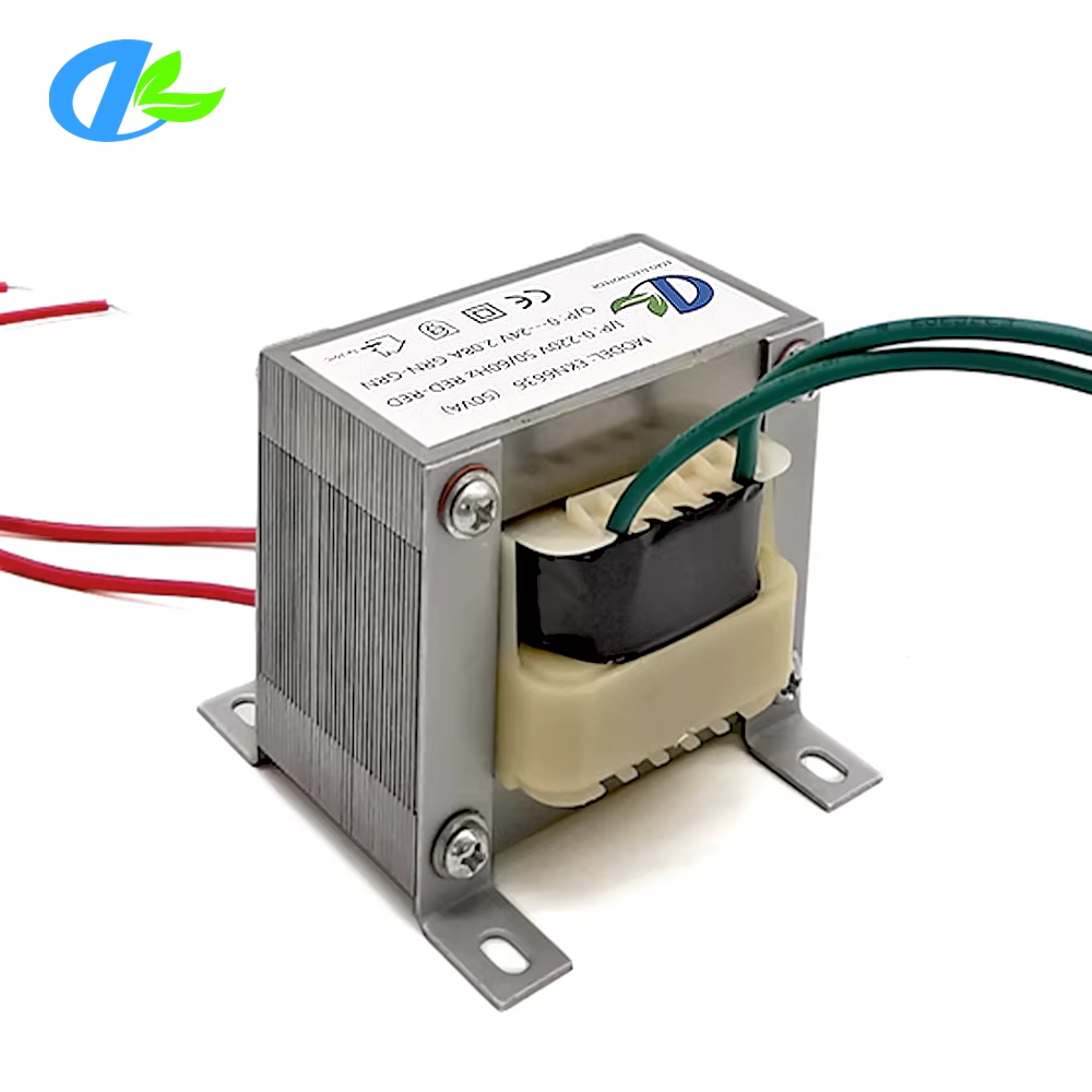
Selecting the Right Audio Transformer for Your Application
Key Specifications That Determine Transformer Suitability
Frequency response characteristics define the usable bandwidth of an audio transformer and must encompass the entire frequency range required by the application. High-quality audio transformers for full-range applications typically exhibit flat response from 20 Hz to 20 kHz, with some professional units extending to 100 kHz for headroom. Low-frequency response depends on primary inductance and the impedance of the driving source, while high-frequency response is limited by leakage inductance and winding capacitance. An audio transformer intended for matching impedances in a full-bandwidth system must maintain response within ±1 dB across the audio spectrum, with steeper rolloffs acceptable for specialized applications like subwoofer crossovers or high-frequency horn drivers.
Power handling capability represents another critical specification that must exceed the maximum signal levels expected in normal operation. Audio transformers are rated in watts or volt-amperes, indicating the continuous power level they can handle without saturation or overheating. A transformer operating near its power limit experiences core saturation at signal peaks, introducing distortion and compression. Conservative engineering practice specifies audio transformers with power ratings at least twice the expected maximum signal level, providing headroom for transient peaks and ensuring linear operation. The power rating interacts with impedance levels, as the same transformer may handle different power levels when operated with different impedance ratios due to changes in current and voltage distribution across the windings.
Evaluating Insertion Loss and Distortion Performance
Insertion loss quantifies the signal attenuation that occurs when an audio transformer is inserted into a signal path, resulting from winding resistance, core losses, and impedance matching imperfections. High-quality audio transformers exhibit insertion losses below 0.5 dB at mid-frequencies, though losses increase at frequency extremes where reactive impedances affect matching efficiency. The insertion loss specification must be verified under actual operating conditions, as losses vary with source and load impedance, signal level, and frequency. Manufacturers typically specify insertion loss under optimal conditions with resistive source and load impedances matching the transformer's design values, but real-world applications may involve reactive loads that increase actual losses.
Distortion performance indicates how faithfully an audio transformer reproduces the input signal without adding harmonic or intermodulation components. Total harmonic distortion specifications for professional audio transformers typically range from 0.01% to 0.1% at nominal operating levels, with distortion increasing at higher signal levels as core saturation approaches. Intermodulation distortion, often more audibly objectionable than harmonic distortion, results from non-linear magnetic behavior and should remain below 0.05% in quality audio transformers. The audio transformer's distortion characteristics depend strongly on signal level, frequency, and the impedance of connected circuits, requiring careful attention to operating conditions during selection and implementation to ensure the chosen transformer maintains acceptable linearity throughout its working range.
Implementation Techniques for Optimal Impedance Matching
Proper Connection Methods and Wiring Practices
Correct wiring of audio transformer connections ensures optimal impedance matching and signal transfer. Balanced connections using the center-tapped windings common in professional audio transformers provide common-mode noise rejection and ground loop elimination. The primary winding connects to the source device with proper attention to phase relationships, typically marked with dots or numbers on the transformer schematic. For balanced operation, the center tap connects to circuit ground or chassis ground depending on the grounding scheme, while the winding ends carry the balanced signal. Secondary winding connections follow the same conventions, maintaining phase relationships and grounding practices appropriate to the receiving device.
Wire gauge and connection quality directly affect the impedance matching accuracy achieved with an audio transformer in practice. Undersized wiring introduces series resistance that alters the effective impedance presented to connected equipment, degrading matching accuracy and increasing insertion loss. Professional installations use wire gauges appropriate to the current levels involved, with larger conductors required for low-impedance, high-current applications like speaker matching. Solder joints must be clean and mechanically sound, as poor connections introduce contact resistance and potential intermittent behavior. Terminal blocks and connectors should provide secure, low-resistance connections with proper strain relief to prevent mechanical stress on transformer leads that could cause failures over time.
Addressing Grounding and Shielding Considerations
Grounding strategy plays a crucial role in realizing the isolation benefits of audio transformer implementation. The magnetic coupling in an audio transformer provides DC isolation between primary and secondary circuits, breaking ground loops that cause hum and interference in systems with multiple ground paths. Proper grounding requires connecting equipment chassis grounds at a single point while allowing the audio transformer to isolate signal grounds between devices. In some applications, the transformer's electrostatic shield connects to ground to intercept capacitively coupled noise, providing an additional layer of interference rejection beyond the magnetic isolation inherent in transformer operation.
Electromagnetic interference susceptibility requires attention to transformer mounting location and orientation relative to other magnetic field sources. Power transformers, motors, and high-current conductors generate magnetic fields that can couple into audio transformers, inducing hum and noise in the signal path. Mounting audio transformers at right angles to potential interference sources minimizes coupling, while physical separation provides additional protection. Mu-metal or other high-permeability magnetic shields can enclose particularly sensitive audio transformers in high-interference environments, though well-designed transformers with proper core material and winding configurations often perform adequately without external shielding in typical professional audio installations where basic precautions regarding placement and routing are observed.
Troubleshooting and Optimization of Transformer-Based Impedance Matching
Identifying and Resolving Common Impedance Matching Problems
Frequency response irregularities often indicate impedance matching problems in audio transformer applications. Excessive low-frequency rolloff suggests insufficient primary inductance relative to the source impedance, requiring a larger transformer with more primary turns or higher-permeability core material. High-frequency rolloff points to leakage inductance issues or capacitive loading, addressable through improved winding techniques, reduced lead lengths, or selection of an audio transformer with superior high-frequency characteristics. A mid-band response dip sometimes occurs with reactive loads that create resonances when combined with transformer leakage inductance, requiring damping networks or impedance compensation to flatten the response.
Distortion symptoms provide diagnostic information about impedance matching accuracy and operating conditions. Increased distortion at high signal levels indicates core saturation, suggesting the transformer is underpowered for the application or the DC bias current in the primary circuit is causing core offset. Asymmetrical clipping on positive or negative signal peaks points to DC imbalance in the driving stage or transformer manufacturing defects. Odd-order harmonic emphasis suggests excessive source or load impedance mismatch, where the audio transformer operates significantly outside its design impedance range, while even-order harmonics may indicate core saturation or non-linear magnetic characteristics requiring transformer replacement or operating level reduction.
Measurement and Verification Techniques
Impedance measurement confirms proper matching between source, audio transformer, and load. Using an impedance analyzer or LCR meter, measure the actual input impedance of the transformer primary with the secondary loaded by the target device. This measured value should closely match the source impedance for which the transformer was selected. Similarly, measure the impedance looking into the secondary terminals with the primary driven by the source device. These measurements reveal whether the audio transformer provides the intended impedance transformation and whether reactive components in the source or load significantly alter the impedance relationships from the nominal resistive values typically assumed in specification sheets.
Frequency response verification across the audio spectrum ensures the impedance matching implementation meets performance requirements. Sweep the system with a sine wave generator while monitoring output level with a precision AC voltmeter or audio analyzer, plotting response from 20 Hz to 20 kHz. The resulting curve should remain flat within specified limits, typically ±1 dB for professional applications. Deviations indicate impedance matching issues, insufficient transformer bandwidth, or resonance problems requiring correction. Square wave testing provides qualitative assessment of transient response and frequency extremes, with clean square wave reproduction indicating proper impedance matching and adequate bandwidth. Ringing, overshoot, or tilt in the square wave response points to reactive mismatches or insufficient transformer performance that degrades audio quality in the practical application.
FAQ
What is the difference between impedance matching and impedance bridging in audio systems?
Impedance matching refers to configuring source and load impedances to be equal, which maximizes power transfer between components. This approach was historically common in telephone and broadcast systems operating at 600 ohms. Impedance bridging involves connecting a high-impedance load to a low-impedance source, typically with a 10:1 ratio or greater, which maximizes voltage transfer while drawing minimal current from the source. Modern audio systems predominantly use bridging configurations, with line-level equipment featuring low output impedances driving high input impedances. Audio transformers can implement either matching or bridging configurations depending on the selected turns ratio and the impedances of connected equipment.
Can a single audio transformer match multiple different impedance combinations?
Many audio transformers feature multiple taps on their windings, allowing a single transformer to accommodate various impedance ratios. A speaker matching transformer might offer primary taps at 4,000, 8,000, and 16,000 ohms with secondary taps at 4, 8, and 16 ohms, creating nine possible impedance ratio combinations from one physical device. The different taps utilize different portions of the windings, effectively changing the turns ratio and thus the impedance transformation. This versatility makes multi-tap transformers valuable in applications where flexibility is required or where the exact impedances may vary. However, each tap combination performs optimally only when used with its designed impedances, and using intermediate or non-standard combinations may compromise frequency response, power handling, or distortion performance.
How does transformer core material affect impedance matching performance?
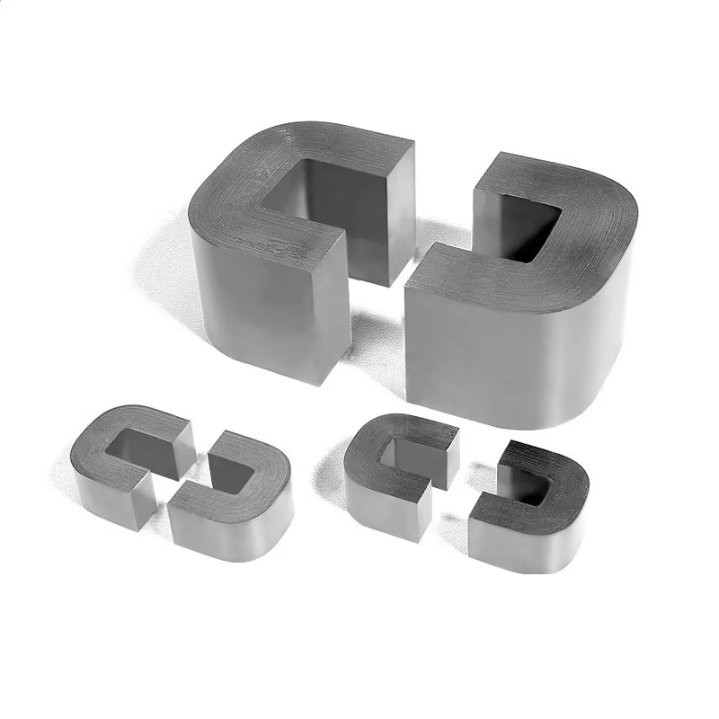
Core material directly influences the magnetic properties that determine audio transformer performance in impedance matching applications. Silicon steel laminations provide excellent performance across the audio spectrum with good saturation characteristics for moderate power levels. Nickel alloys like permalloy or mumetal offer higher permeability, enabling better low-frequency response in smaller packages but at higher cost. Amorphous and nanocrystalline materials provide extremely low core losses with high saturation flux density, delivering superior performance in demanding applications. The core material selection affects primary inductance, which determines low-frequency response in conjunction with source impedance, and saturation characteristics, which limit maximum signal handling before distortion occurs. Proper core material selection ensures the audio transformer maintains linear operation and frequency response flatness across the impedance transformation range required by the specific matching application.
What happens if I use an audio transformer with the wrong impedance ratio?
Using an audio transformer with an incorrect impedance ratio produces several detrimental effects on system performance. Frequency response suffers as impedance mismatches create reflections and losses that vary with frequency, causing peaks and dips in the response curve. Power transfer efficiency decreases, with signal levels lower than expected due to impedance mismatch losses. Distortion may increase as the transformer operates outside its optimal loading conditions, potentially experiencing core saturation at lower signal levels than its rating would suggest. In severe cases, equipment damage can occur if the mismatched impedances cause excessive current draw or voltage stress on connected components. The specific consequences depend on how far the actual impedances deviate from the transformer's design values, with larger mismatches producing more severe degradation. Proper impedance ratio selection based on careful measurement or specification verification of source and load impedances prevents these problems and ensures optimal performance.
Table of Contents
- Understanding Impedance and Its Impact on Audio Systems
- Calculating Impedance Transformation Ratios
- Selecting the Right Audio Transformer for Your Application
- Implementation Techniques for Optimal Impedance Matching
- Troubleshooting and Optimization of Transformer-Based Impedance Matching
-
FAQ
- What is the difference between impedance matching and impedance bridging in audio systems?
- Can a single audio transformer match multiple different impedance combinations?
- How does transformer core material affect impedance matching performance?
- What happens if I use an audio transformer with the wrong impedance ratio?